Our experience working with and analyzing aircraft electronics and avionics has identified a process for converting real flight hardware and control panels into modules that can be connected to a flight simulator. Currently, these projects target consumer and professional simulator software programs such as Microsoft Flight Simulator and X-Plane. However, the goal of these conversions is to get the control panels communicating with a computer, generally over USB, serial, or CANBUS. From there, the software interface can be customized to communicate with virtually any flight simulator program, or be used in scenarios beyond flight simulators. Here are some examples of real aircraft control panels that we have converted for use in computer-based flight simulators.
Cabin Ancillary Control Panel
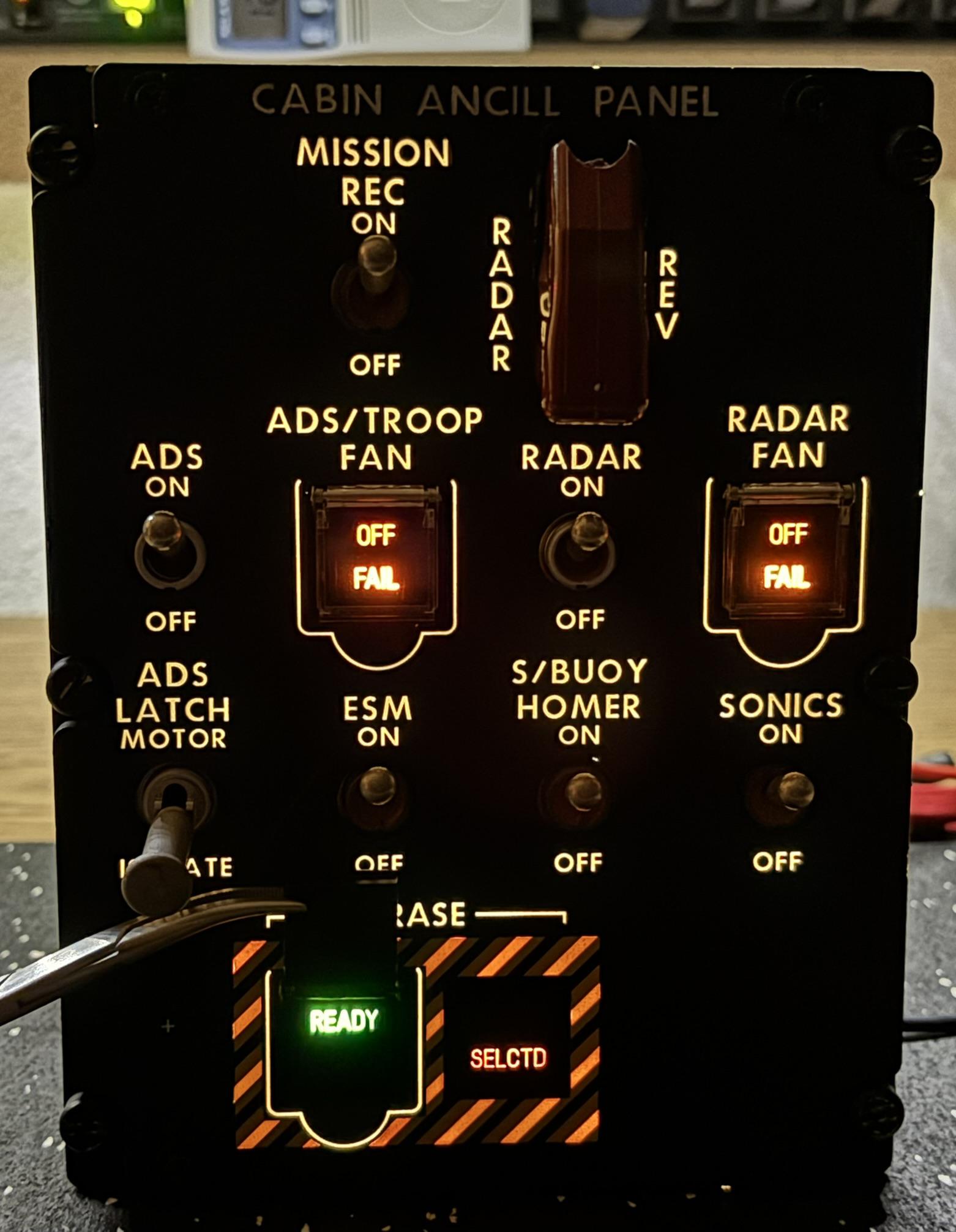
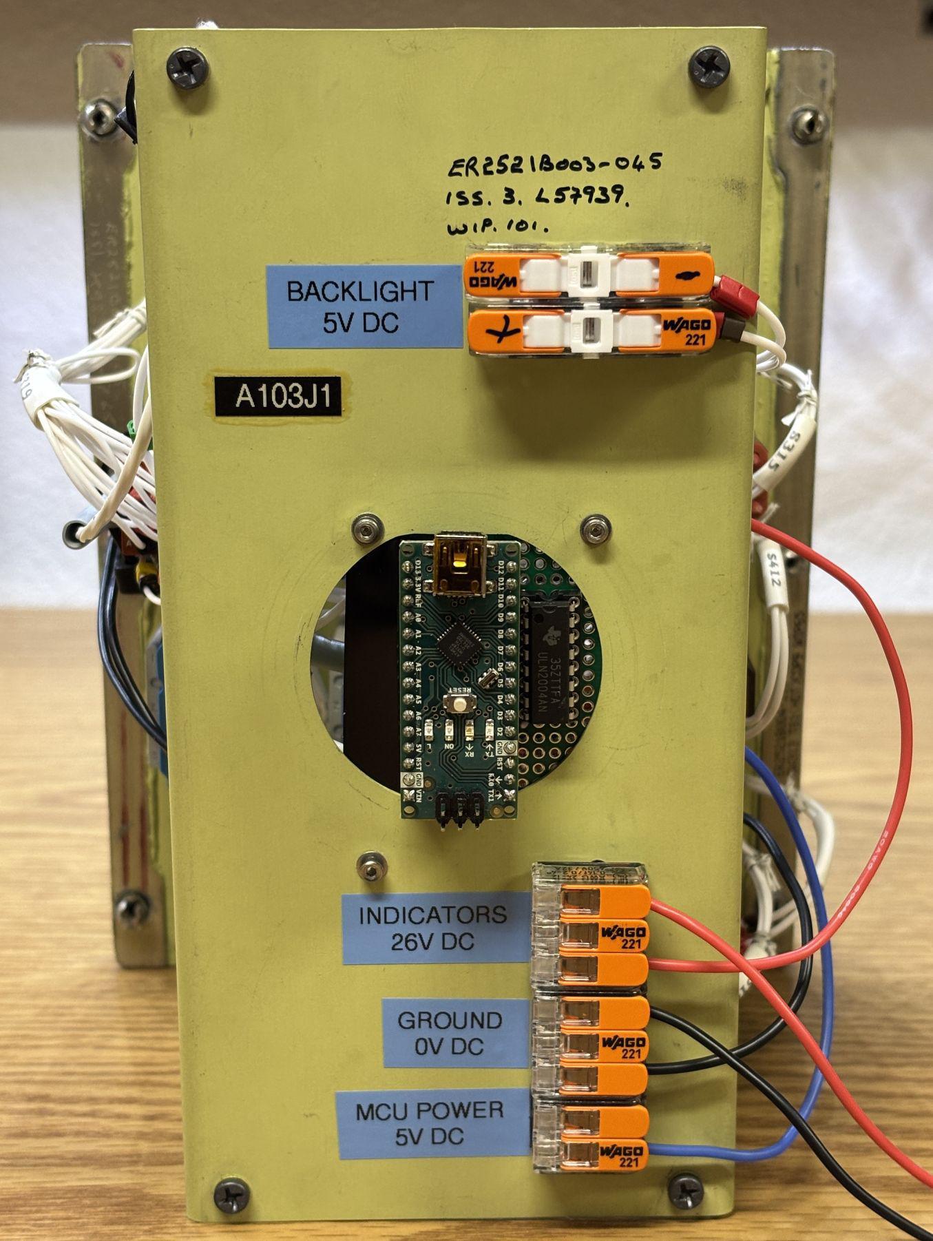
This is a cabin ancillary panel from an unknown aircraft. It was a great candidate for conversion because the switches and indicators all had discrete connections to the rear connector. The connector was removed and replaced with a custom board. On the board is an Arduino Nano and a ULN2004AN. All switches and indicators have their connections soldered to this board. The ULN drives the incandescent indicators while the Arduino monitors the states of the switches directly. Using a serial interface, the indicator states are fully controllable over serial and the switches can be be monitored individually. A lamp test function is also provided to illuminate all indicators simultaneously. The backlight wires were brought out to Wago connectors on the back panel for easy integration.
Panavia Tornado External Lighting Control Panel
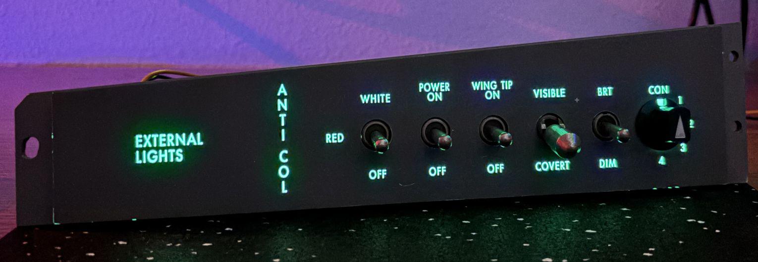
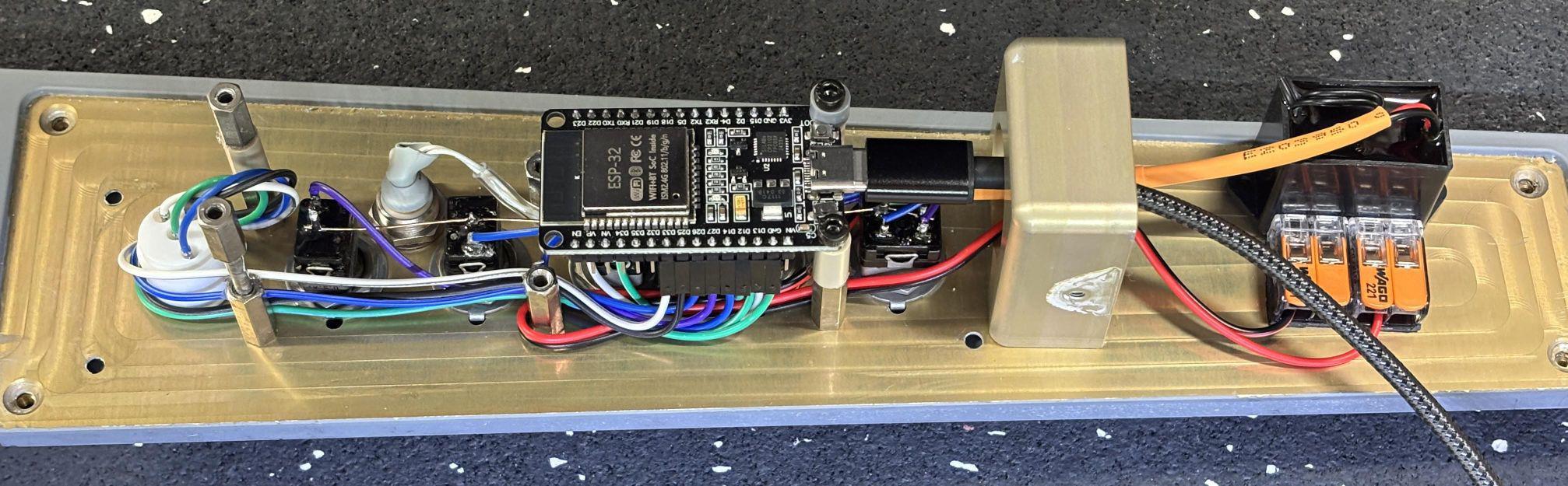
This is an external lighting control panel from a Panavia Tornado aircraft. The panel has five toggle switches and one rotary switch, so conversion was straightforward. The internal stack of circuit boards was removed and replaced with just a single ESP32 microcontroller. The connector and harness was also removed. Pins of the ESP-32 were mapped individually to wires that we soldered to the switches and rotary encoder. The software reports the status of all switches and the rotary selector over a serial interface to the computer. A small high-voltage electroluminescent driver module was adhered to the panel to drive the backlight. The ESP-32 can be powered over USB and the backlight driver can be powered by 12V DC. These components fit nicely under the existing cover without any major modifications.
Racal Avionics JTIDS/NATO Link-16 Interface Unit
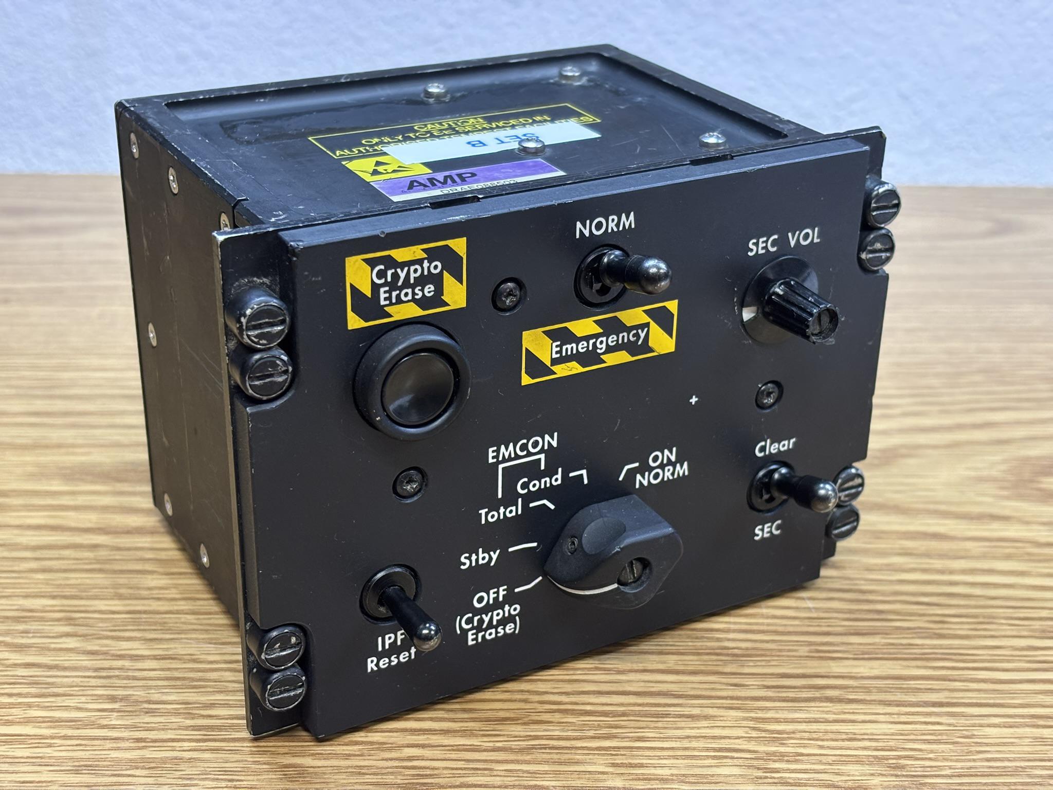
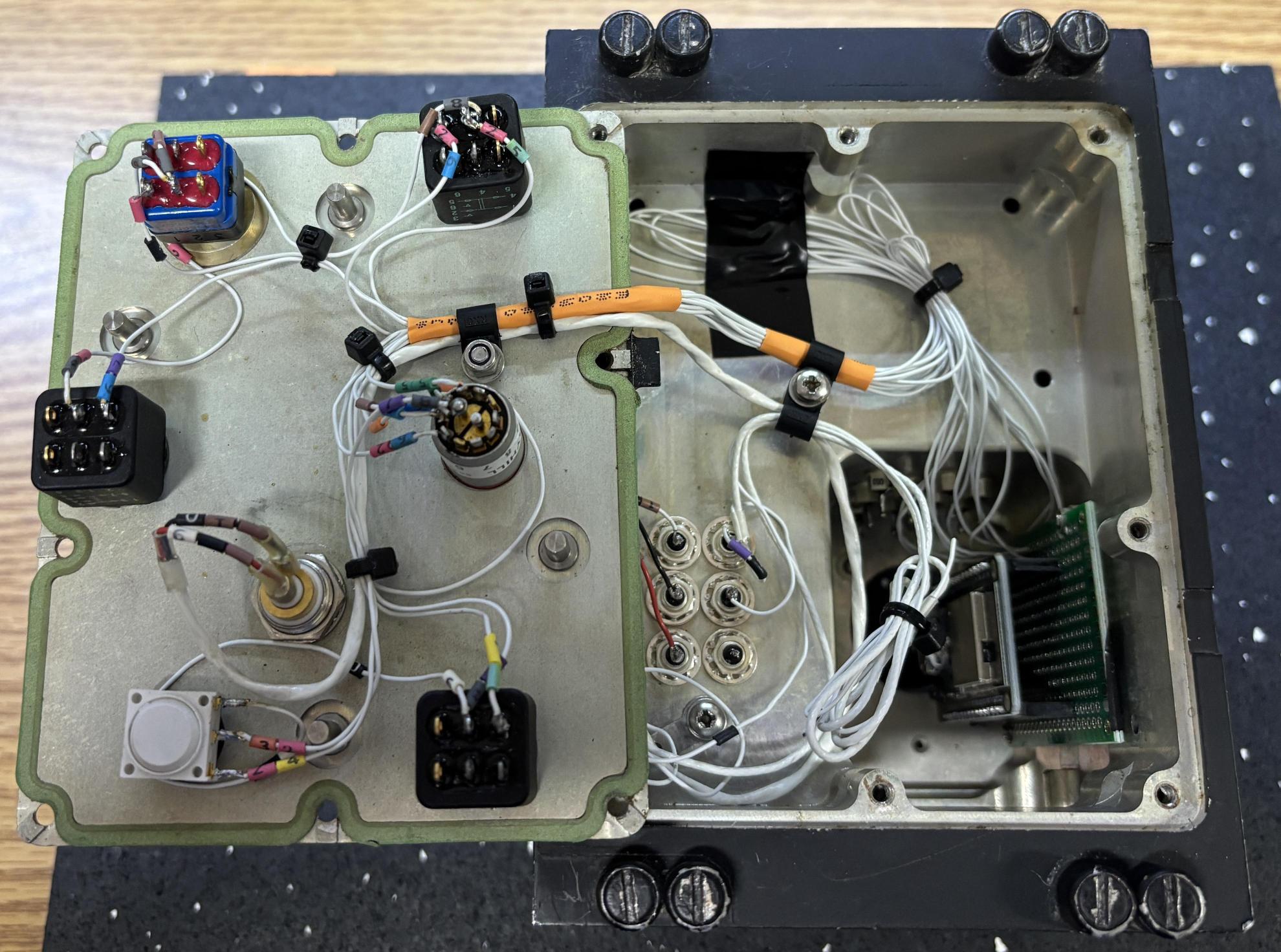
This is a Link-16 secure communications control panel from an unknown aircraft. It has no indicators and just consists of three toggle switches, a rotary selector, a momentary pushbutton, and a potentiometer. All internal boards were removed and an ESP-32 mounted to a custom PCB was installed in place of one of the OEM boards. The entire wiring harness was removed and a new one was assembled to connect each control to pins on the ESP-32. The software reports the status of all controls to the computer over a serial interface. The ESP-32 is powered over USB and the backlight has a dedicated connection on the rear panel.
BAE Systems Radio and Key Selection Panel
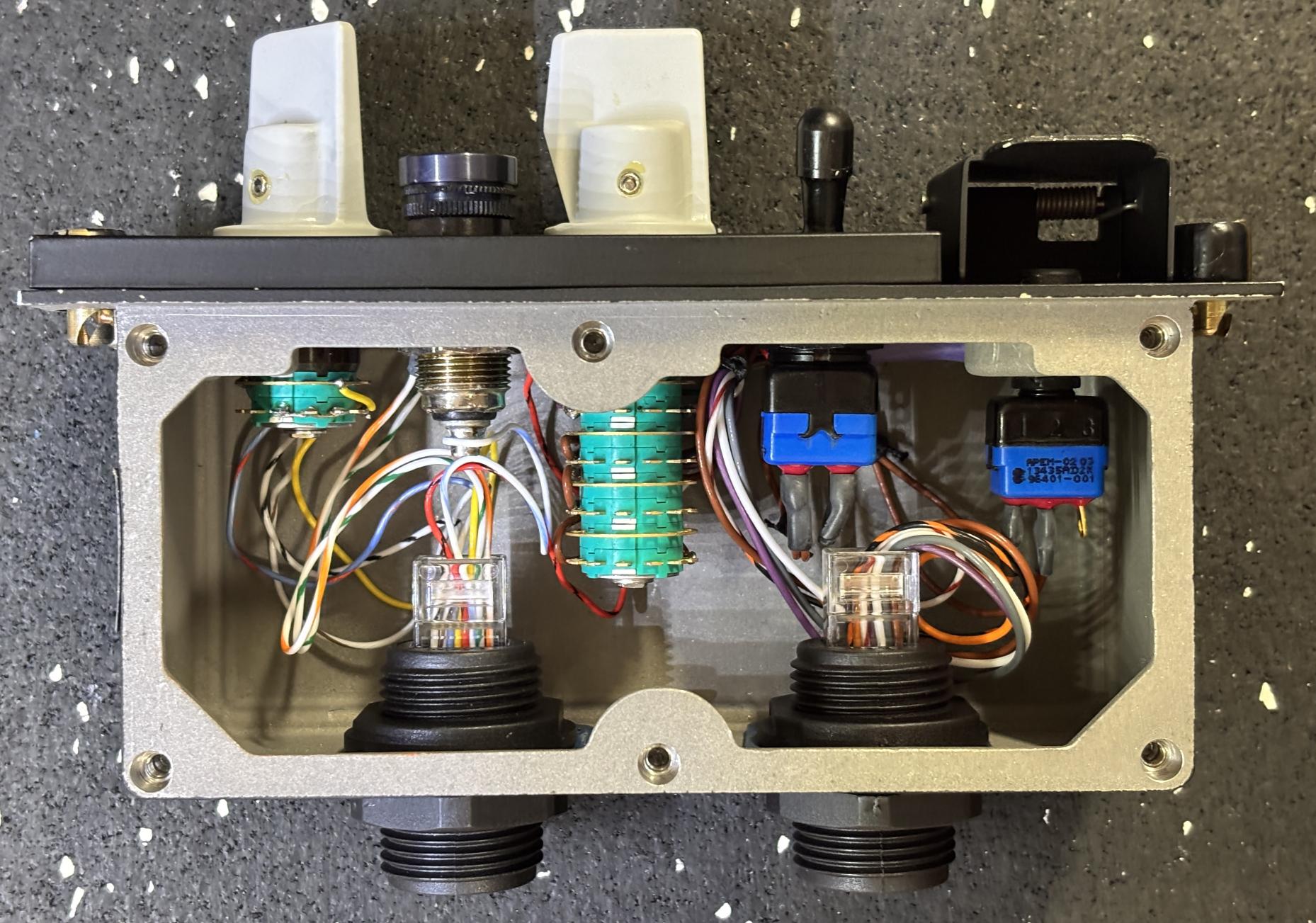
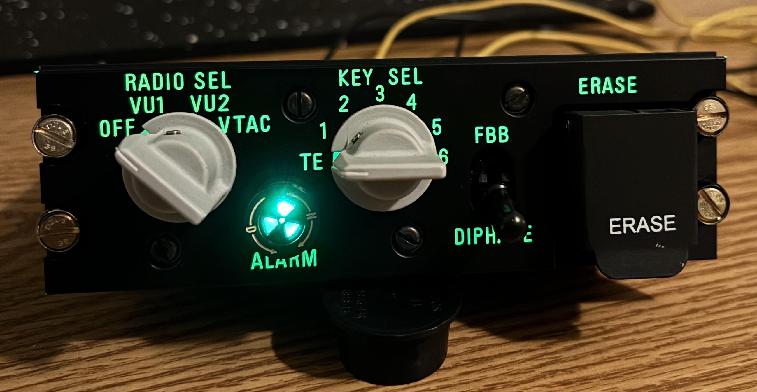
This is a radio and key selection control panel. It has just two rotary selector switches, a momentary pushbutton, and an alarm indicator. Due to the fact that a microcontroller would not fit within the casing, the existing wiring harness was retrofitted to terminate into two RJ-45 connectors. This allows the control panel to be connected to a dedicated or multipurpose controller board over two standard Ethernet cables. There is no digital communication, only discrete connections for the switches and indicator. An Arduino or ESP-32 can then be used on a remote board to monitor the switch positions and report their status to a computer, along with controlling the state of the indicator.