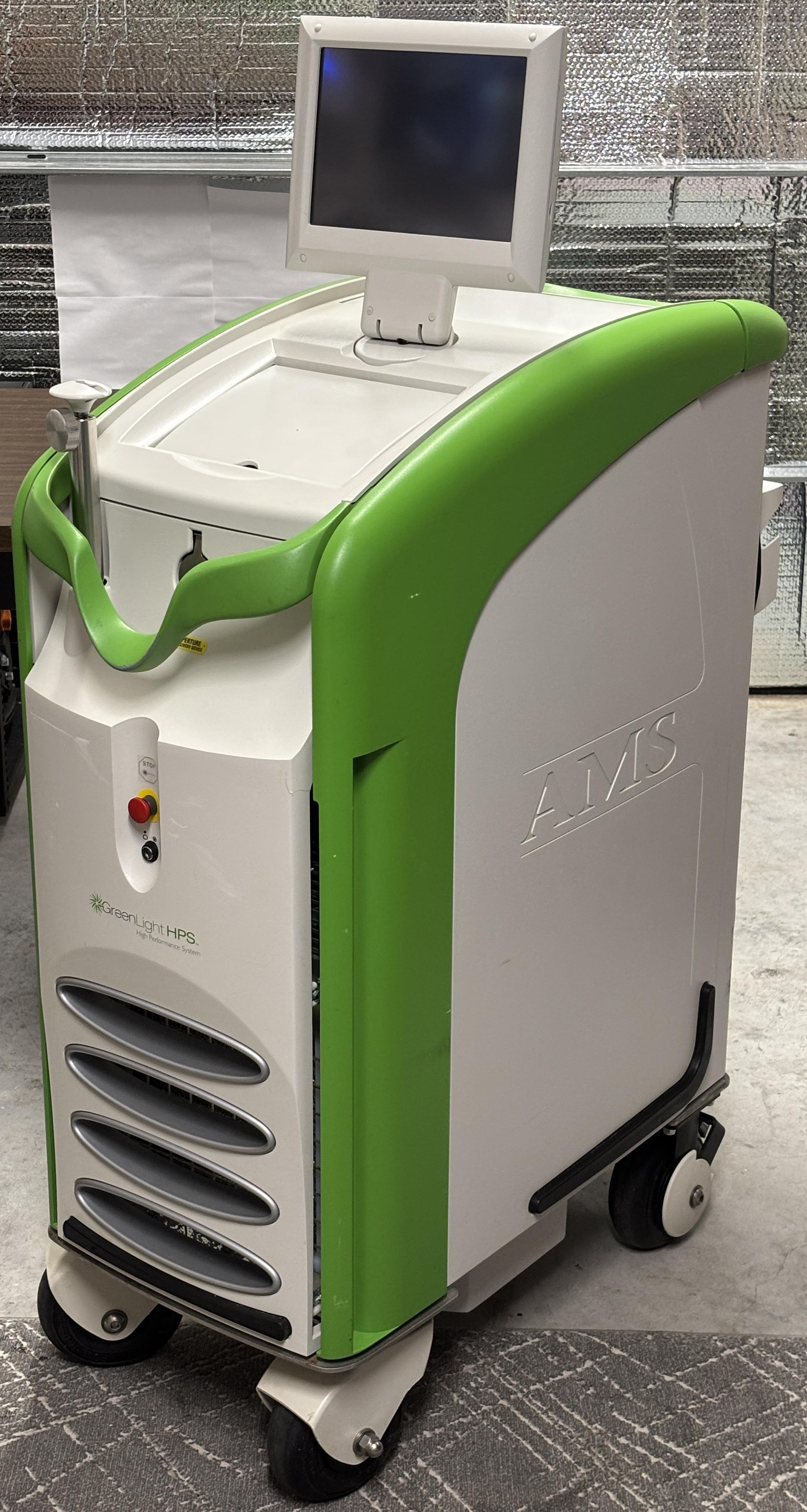
The Greenlight HPS is a medical laser system manufactured by AMS (American Medical Systems - now Boston Scientific). The device was originally manufactured by Laserscope, who was acquired by American Medical Systems in 2006. It's a pulsed 532nm green DPSS laser with a maximum CW output power of around 120 watts. Output energy is measured in joules and can be significant depending on the selected setpoint and pulsed operation. The device is used to treat benign prostatic hyperplasia (BPH) and other urological conditions by delivering controlled pulses of high energy laser light to target areas. Specifically, this process is used for anti-coagulation therapy and tissue vaporization. The 532nm wavelength was chosen specifically due to its absorption in tissue and its resistance to negative effects introduced by irrigants during the procedure. Compared to other procedures such as TURP or surgery, the Greenlight is equally as effective, less invasive, and generally results in fewer complications. The laser beam can be fired in two modes, vaporize and coagulation, depending on the situation. This information was pulled from the Greenlight HPS brochure and operator's manual. The Greenlight HPS probably cost around $150,000 new, and was only intended to be sold directly to hospitals and medical professionals. Like most products in the medical industry, they get outdated quickly, as soon as the next model comes out. Therefore, plenty of these systems ended up at electronics recyclers and scrap yards. This particular unit was purchased online for a fraction of the original sale price, and it was in excellent condition.
SAFETY CONSIDERATIONS: As Photonicinduction would say (paraphrased): If you touch that output, you will be dead before you hit the floor, there is so much energy that you will probably just explode. Well, not necessarily, but the beam from a Laserscope has the potential to reach 120 watts CW, and many kW when pulsed operation is considered. It's a class 4 laser, but that really doesn't do it justice. Since this is a pulsed laser, the output power has the potential to massively exceed the rated CW power. Coming in contact with that beam will of course obliterate your remaining eye, and the eyes of those around you. This can happen even if you don't stare into the beam path. Even scattered or indirect reflections from this system can cause permanent damage and vision loss. Additionally, an uncontrolled beam has the potential to cause severe burns, ignite objects, burn the wall, and cause various damage to the surrounding area. Even at idle, the 808nm pump diode within the resonant cavity can still cause eye damage and burn objects put in the beam path (we tested this). There is a reason why this device has so many interlocks, so exercise more caution than you ever have if you ever get the pleasure (or displeasure) of working with a Laserscope. Also, if that wasn't enough, there are plenty of high voltage components within the cabinet along with a large moving fan in the chiller, which would be more than happy to remove a digit or two. You probably get the point by now, be VERY careful!
System Overview
The Greenlight HPS weighs around 335 lbs. It's a beast, but luckily is on wheels and can be rolled around. These were meant to be transported around hospitals, and not necessarily restricted to just one operating room. There's an internal steel frame that is surrounded by plastic panels and painted metal accents and handles. Depending on your taste, it's somewhat stylish, but would benefit from a new paint job, in our opinion.
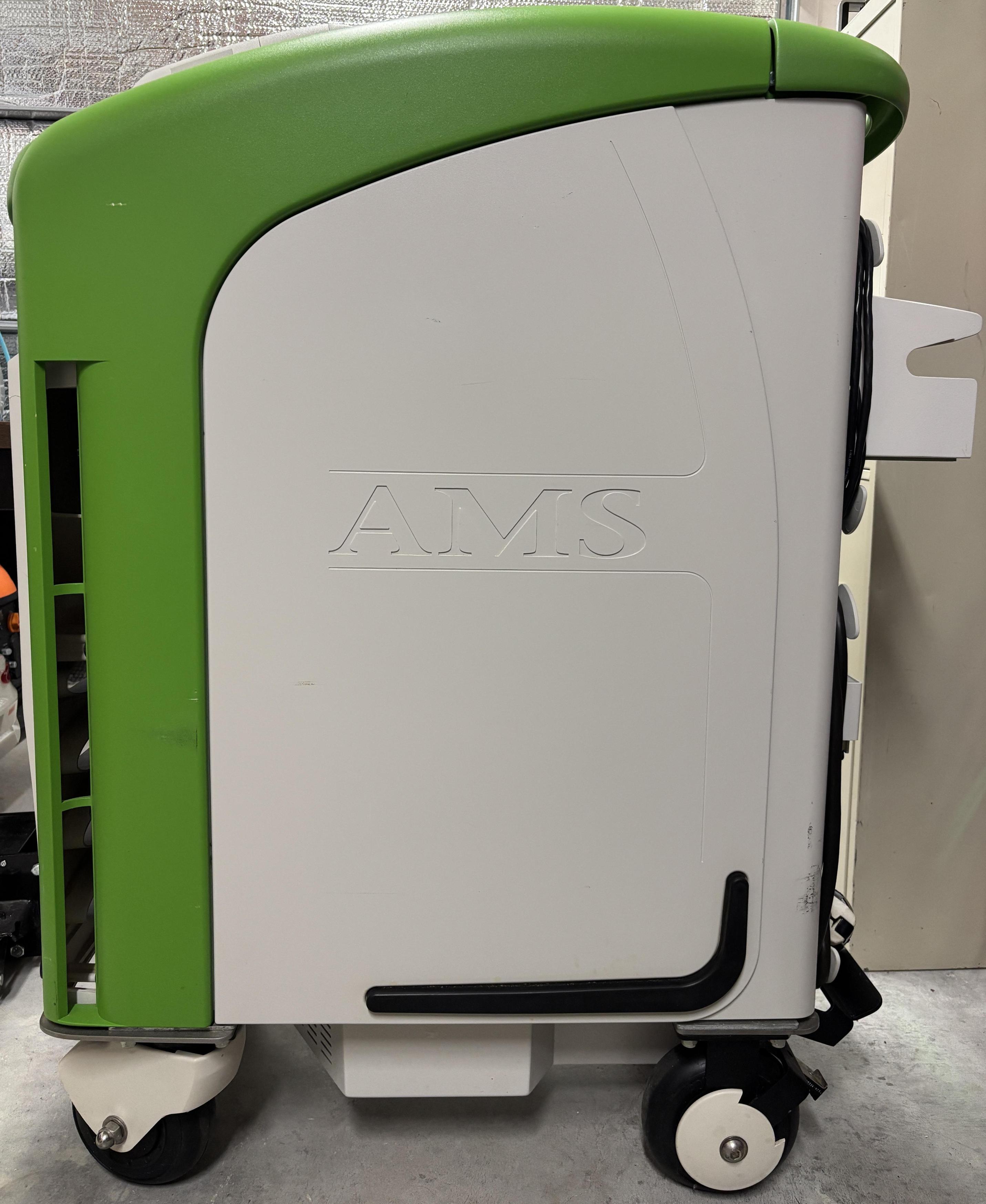
On the back is a green metal handle, which helps with maneuvering the unit. Below that is an information sticker and some warning labels. Hanging on some clips is the foot switch assembly, which can conveniently be attached to the unit when not in use. There are retainers for the cables to keep them off the floor when the system is not in use. Towards the middle-left is the foot switch connector (9-pin circular Amphenol) and a 2-pin external interlock plug. Below that, also on the left, is the coolant fill reservoir. This is not the main reservoir, but is where coolant is added. On the bottom left is the coolant drain port, which uses a CPC quick-disconnect fitting with a built-in valve. On the bottom right is the circuit breaker, which is complemented by the power cord that exits through the center of the bottom. This system arrived with a 50-amp Hubbell plug which we replaced with the factory-recommended NEMA L6-30R plug. The Greenlight HPS requires 200-240 VAC @ 50/60 Hz and requires a 30 amp circuit. Along with the wheels, there is a built-in foot-actuated brake that keeps the unit from rolling away when parked.
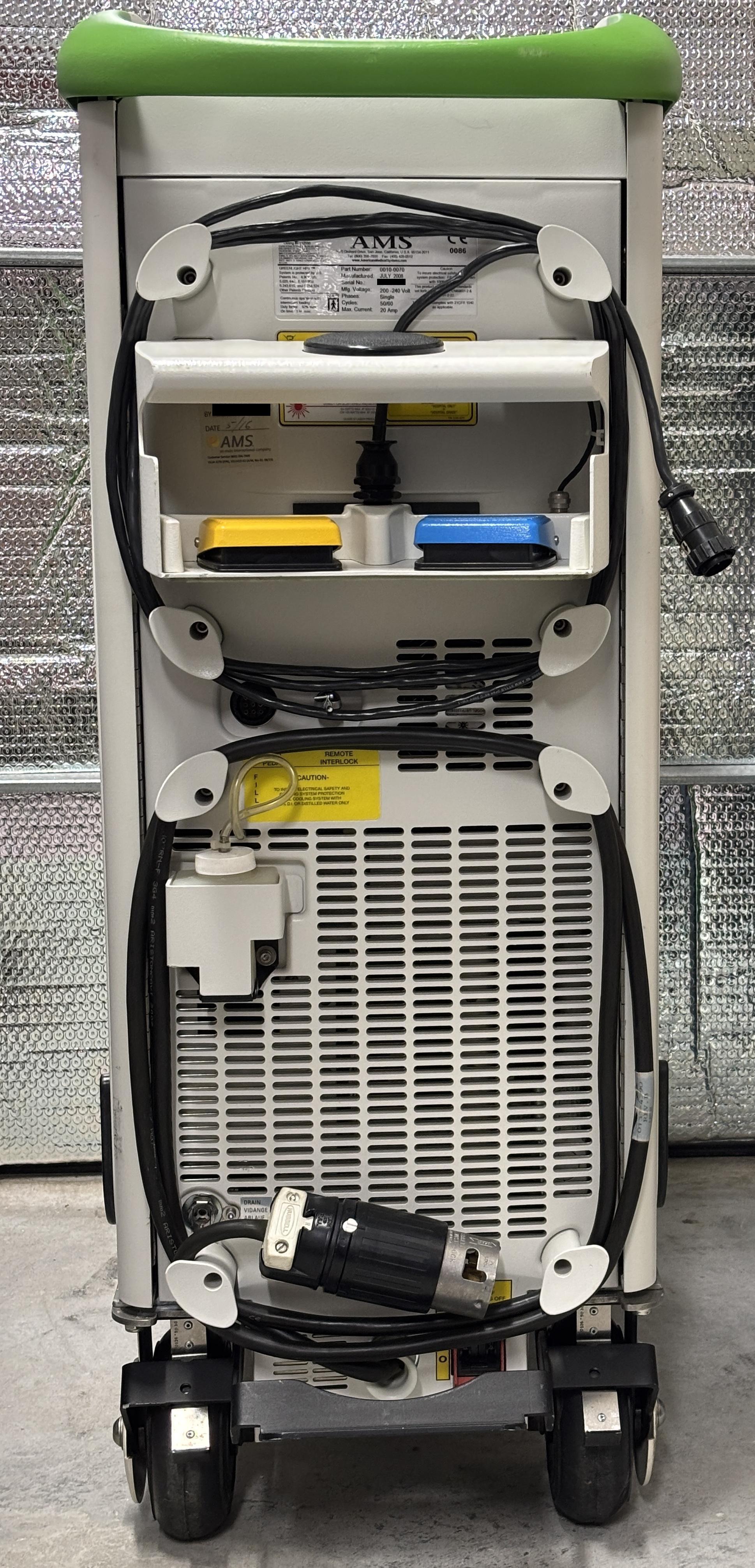
Both side panels are actually doors that swing out and allow access to the internal components. AMS actually refers to the locking mechanism for the doors as "tamper-proof fasteners". This is nonsense as they're just Philips thumbscrews along the front side of each door, placed directly behind the front fascia. They can be accessed with a long screwdriver or your fingers by inserting them through the vertical slots at the front portion of each door. Each door has four thumbscrews. A good amount of effort was put into EMI shielding as evident by the metal covering on the inside of the doors along with the copper tape towards the back.
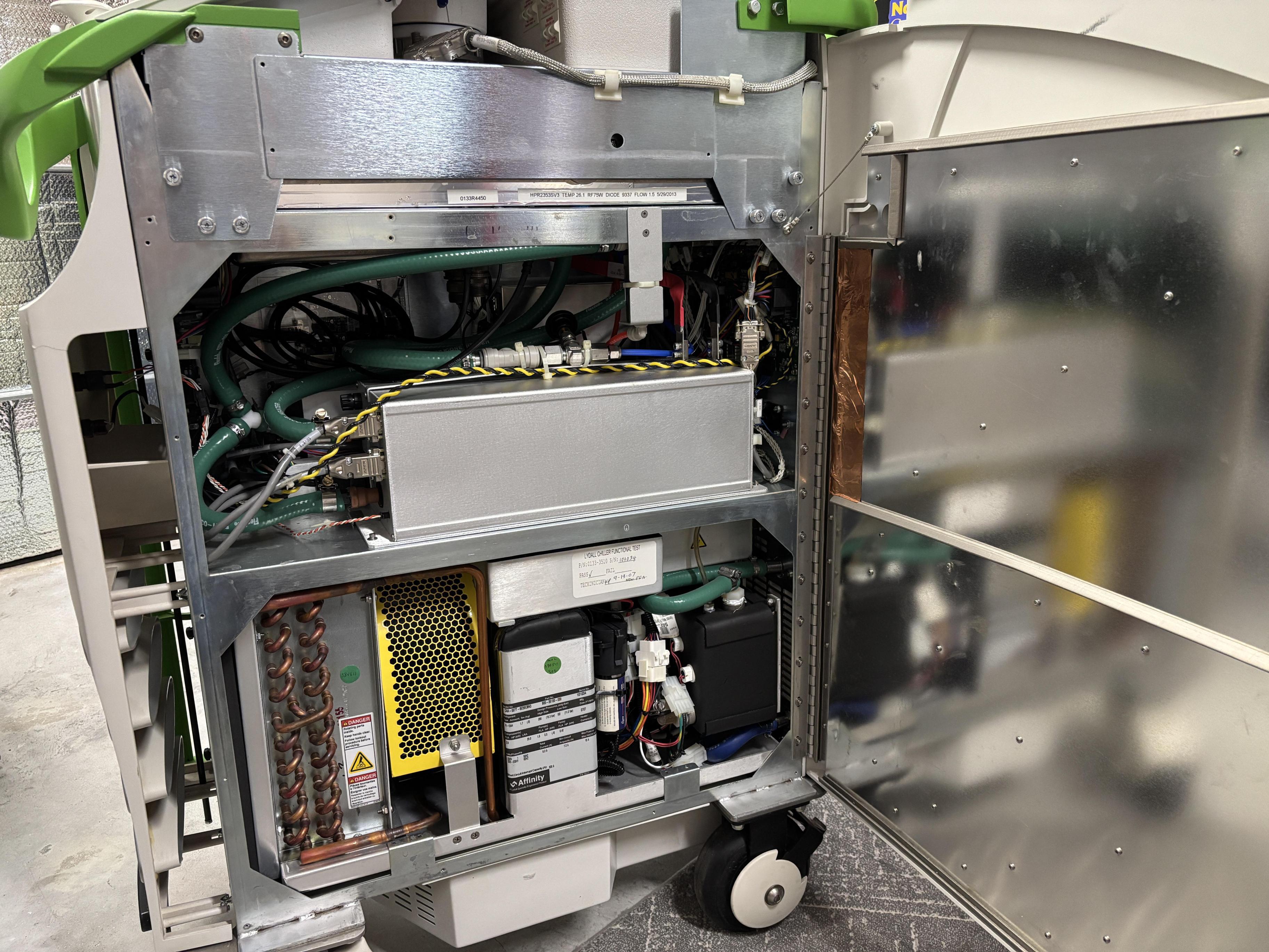
Inside the cabinet, there are two major sections. The upper section houses the laser driver, q-switch driver, and control electronics. The lower section is solely occupied by the chiller.
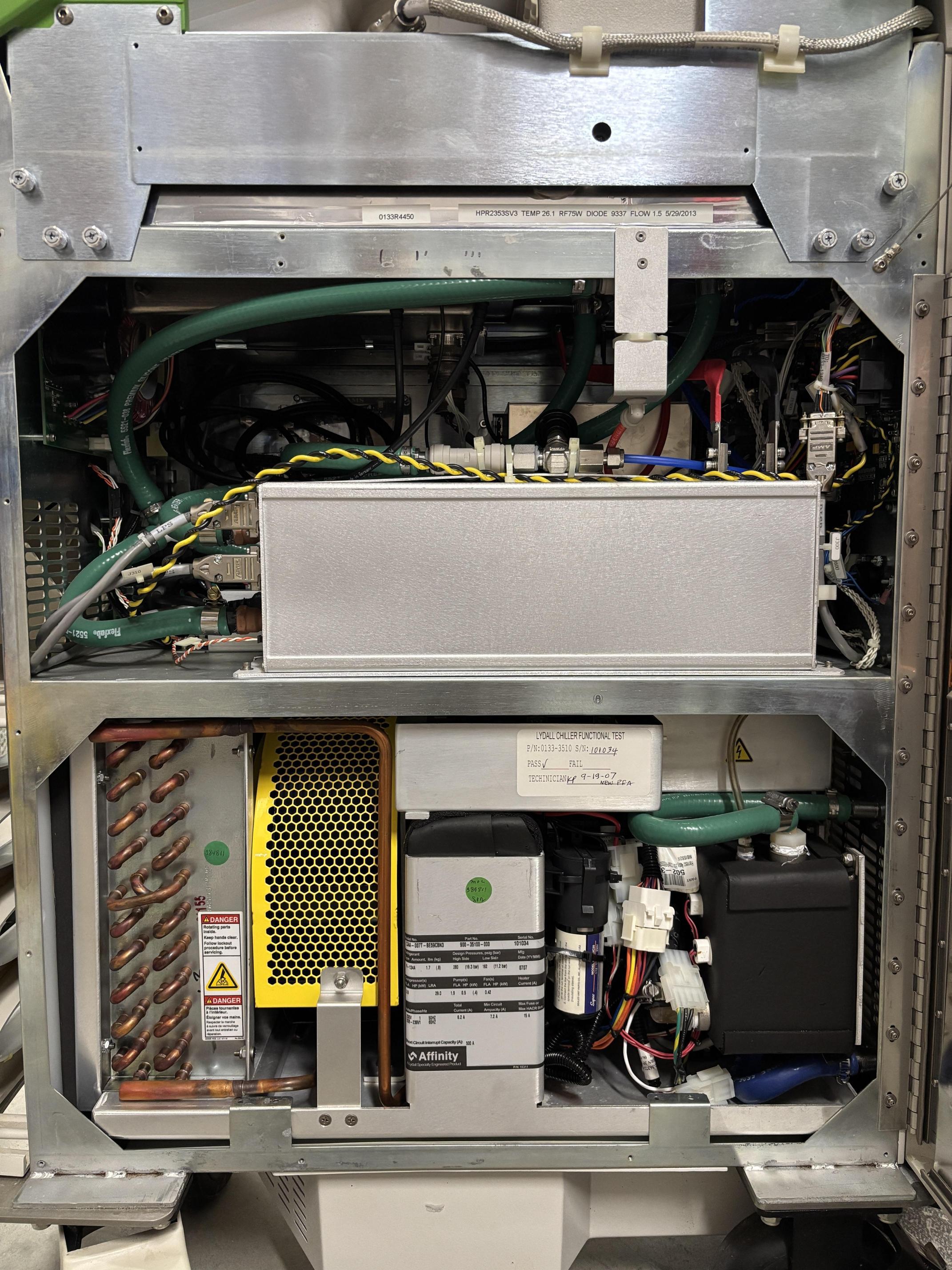
On the other side, the upper section is hidden by a hinged cover. The other side of the chiller is visible within the lower section.
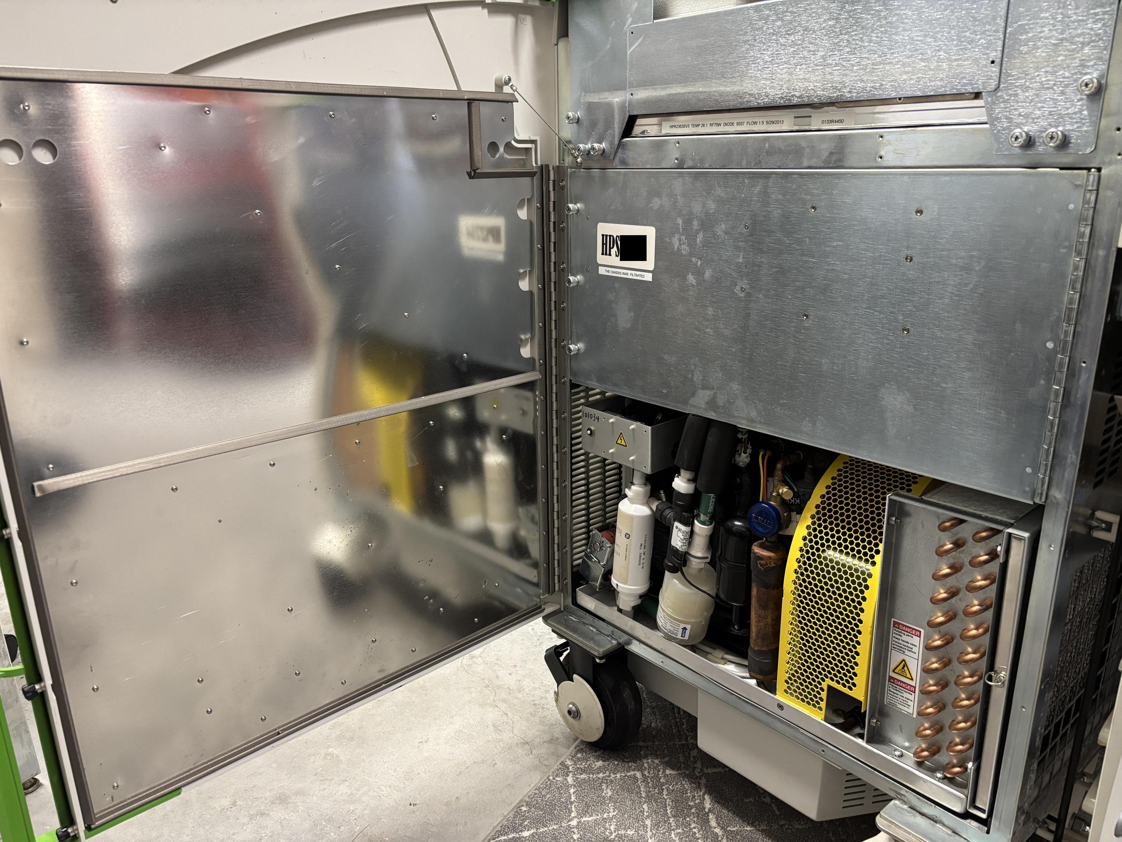
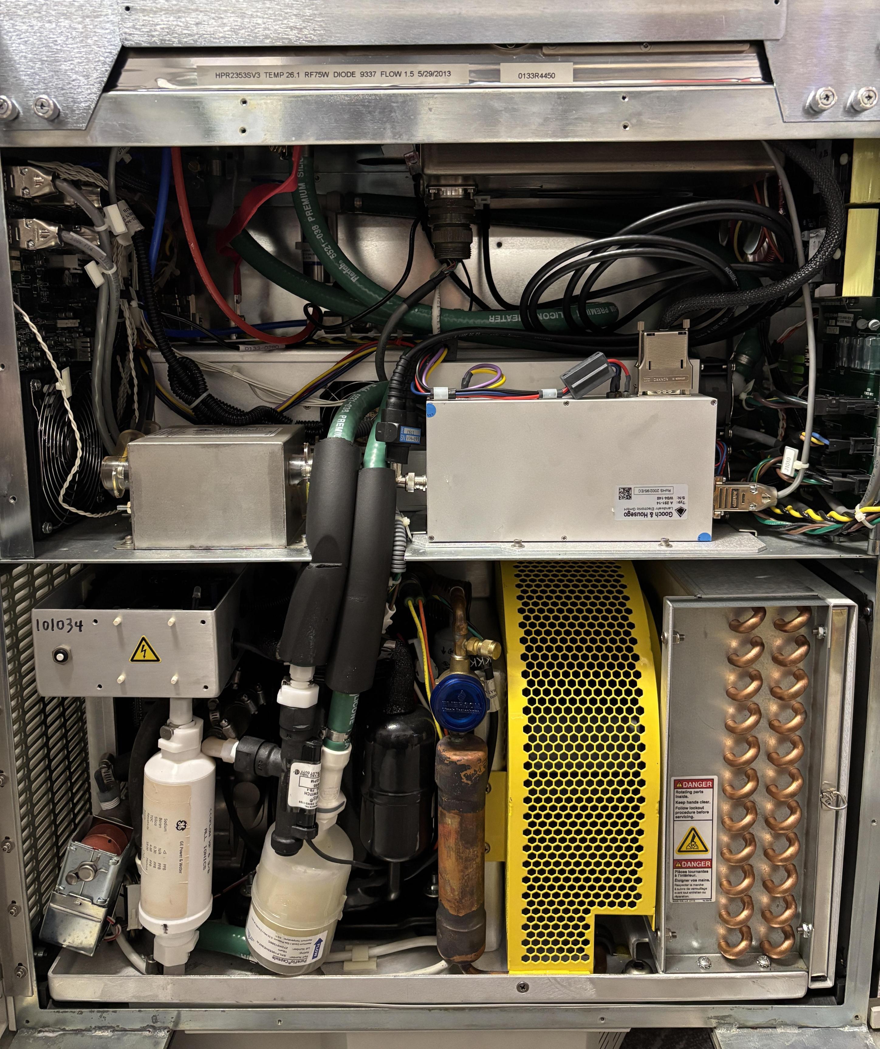
With the hinged cover moved out of the way, we can get a view of the upper section control electronics on this side. Some plumbing, numerous wiring harnesses, and the aforementioned driver modules are visible, along with an AC line filter. It's a very densely packed system, but surprisingly isn't bad to work on. Most modules can be removed easily after disconnecting their connections and removing a few screws.
On that hinged panel are two components: the data logging board (DLB) (left), and the low-voltage DC power supply (right).
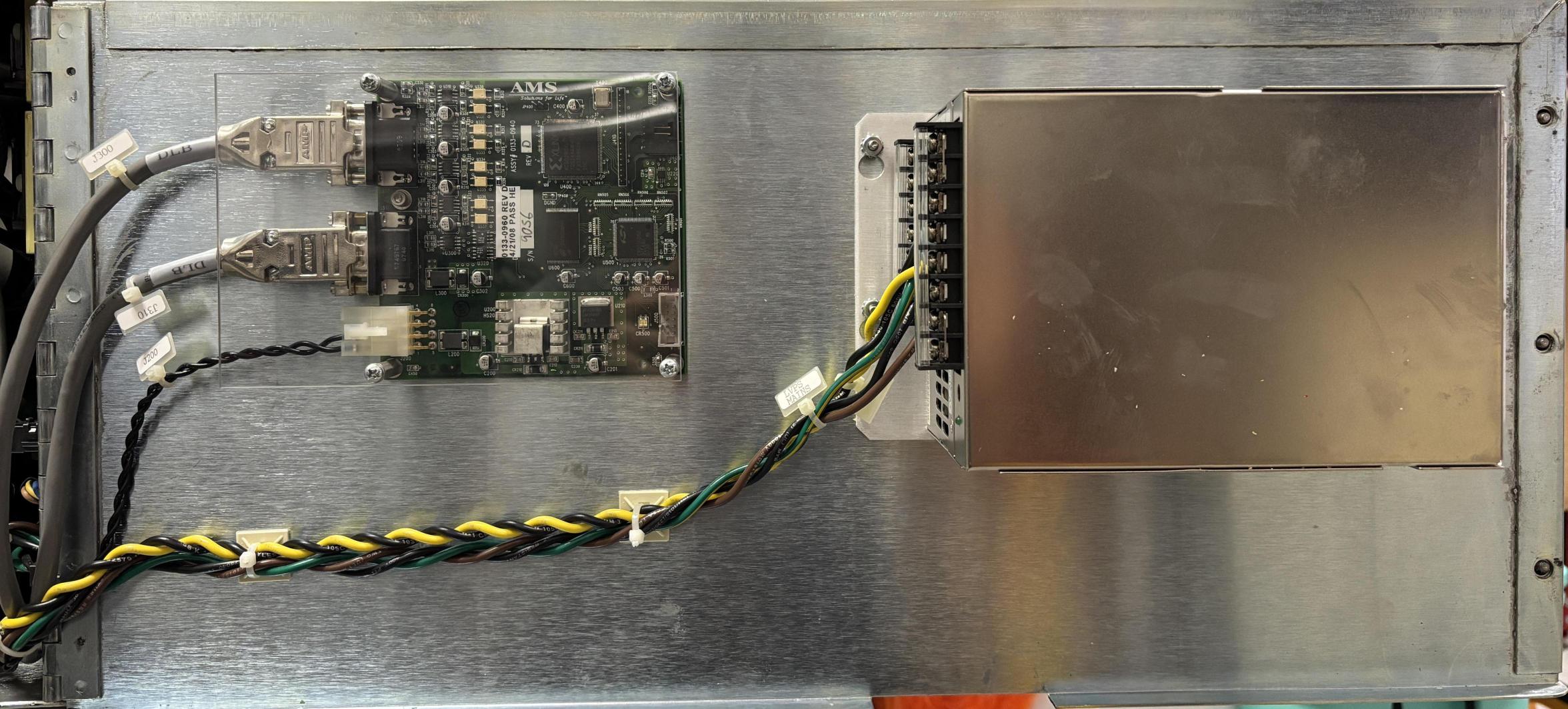
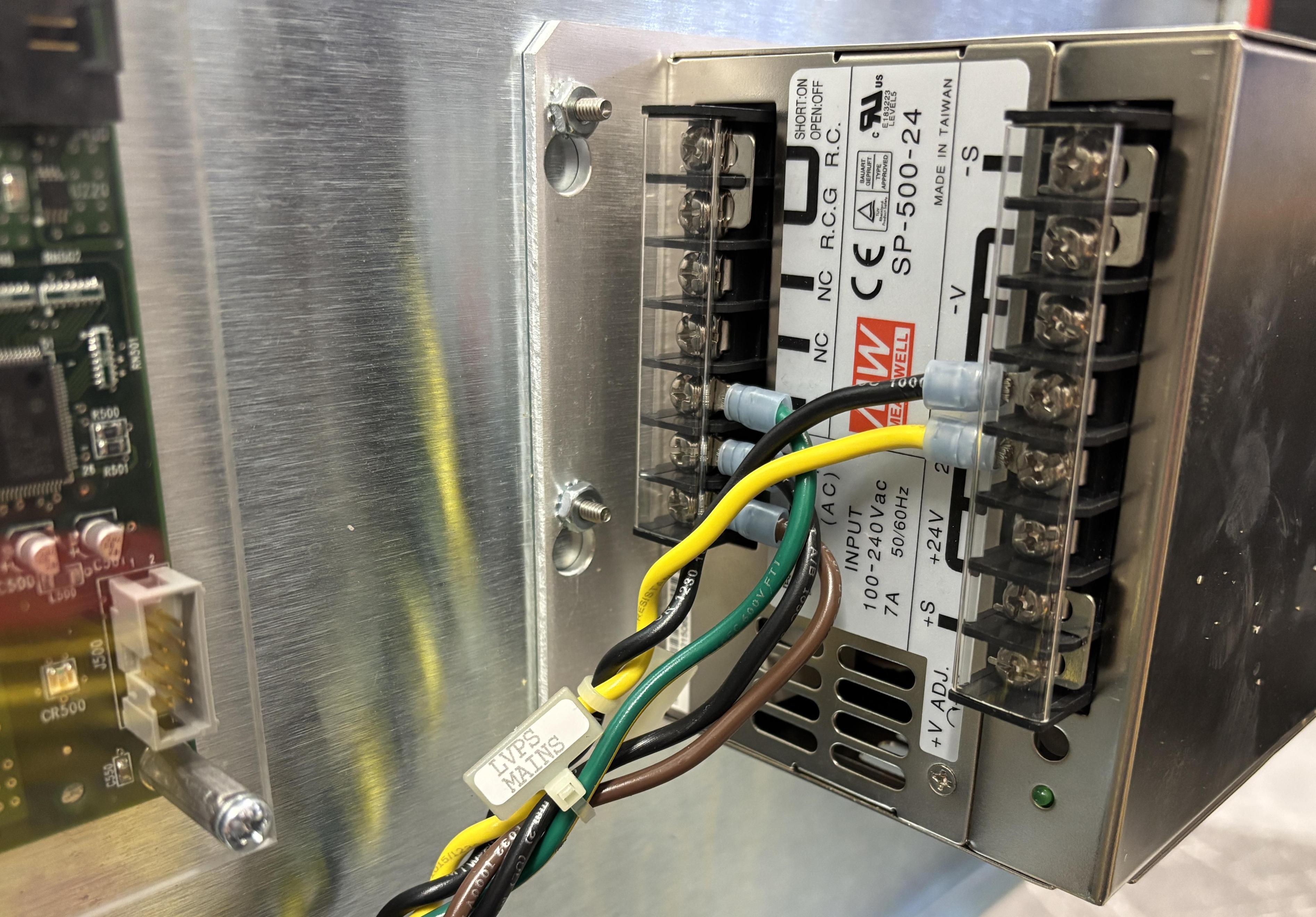
The low-voltage DC power supply is a MEAN-WELL SP-500-24 which accepts the 240V AC input and supplies 24V DC to the control electronics. The output of this power supply goes directly to the rear panel board (RPB), which distributes it further throughout the system.
Below is an ASCII side elevation diagram of the Greenlight HPS that illustrates the main components and their locations.
            FRONT  ◄───────────────────────────────────────►  REAR

                           ┌───────────────────┐
                           │▒▒▒ 			▒▒▒│
						   │▒▒▒ TOUCHSCREEN ▒▒▒│
						   │▒▒▒  			▒▒▒│
                           └─────────┬─────────┘
                                     │  tilt / swivel arm
      ╭──────────────────────────────┴──────────────────────────╮
      │ ┌─────────────────────────────────────────────────────┐ │
      │ │ LASER RESONATOR — sealed optical bench              │ │
 ┄┄┄╞═╪═╡ ◙──╡SHTR╞══╡DBLR╞══╡Q-SW╞══╡ Nd:YAG rod ╞═══█       │ │
  ▲   │ │  ▲   safety  532nm   AOM        ▲            HR mir │ │
  │   │ │  └ fiber launch / coupling      └ diode pump bar    │ │
  │   │ └───────────────────────────────────────┬─────────────┘ │
  │   │                                         ║               │
  │   │  ┌──────────────────────────────────────╫────────────┐  │
  │   │  │ CONTROL BOARDS      · interlock CPU  ║            │  │
  │   │  ├──────────────────────────────────────╫────────────┤  │
  │   │  │ LASER DRIVER        · diode current  ║            │  │
  │   │  ├──────────────────────────────────────╫────────────┤  │
  │   │  │ Q-SWITCH DRIVER     · RF out to AOM  ║            │  │
  │   │  ├──────────────────────────────────────╫────────────┤  │
  │   │  │ POWER DISTRIBUTION  · DC rails       ║            │  │
  │   │  ├──────────────────────────────────────╫────────────┤  │
  │   │  │ LINE FILTER         · EMI / mains    ║            │  │
  │   │  └──────────────────────────────────────╫────────────┘  │
  │   │                                         ║               │
  │   │  ┌──────────────────────────────────────╫────────────┐  │
 ≡≡   │  │ CHILLER                              ║            │  │
 ≡≡   │  │   ┌──────┐    ┌───────────┐          ║            │  │
 ≡≡ ──┤  │   │ PUMP ╞════╡ RESERVOIR ╞══════════╝            │  │
 ≡≡   │  │   └───▲──┘    └───────────┘                       │  │
 ≡≡   │  │       ╚═══╡ HEAT EXCHANGER ╞═══╡ FAN ╞════════╗   │  │
      │  │                                               ║   │  │
      │  └───────────────────────────────────────────────╫───┘  │
      │      return from resonator ══════════════════════╝      │
      ╰──┬───────────────────────────────────────────────────┬──╯
    ┌────┴───────────────────────────────────────────────────┴────┐
    │   ISOLATION TRANSFORMER   +   AUTOSELECT BOARD              │
    │   (hangs below cabinet floor pan, between caster mounts)    │
    └──┬────────────────────────────────────────────────────────┬─┘
       │                                                        │
      ═╧═                                                      ═╧═
      (O)                                                      (O)
     front                                                     rear
     caster                                                    caster

  LEGEND
    ┄┄┄  fiber delivery, exits front-panel port
    ═══  coolant loop (supply up to head, return down to chiller)
    ≡≡   front intake louvers / airflow
    ◙    fiber coupling optics      █  high-reflector mirror
    ╡ ╞  optical elements on bench  ▲  pointer to labeled part
Most plumbing connections use CPC (or similar) quick-disconnect fittings with internal valves. This greatly improves the serviceability of the unit and minimizes spills. We removed the chiller to access the electronics and closely inspect it. Only a few fittings need to be released to facilitate this.
Embedded Chiller and Water Cooling System
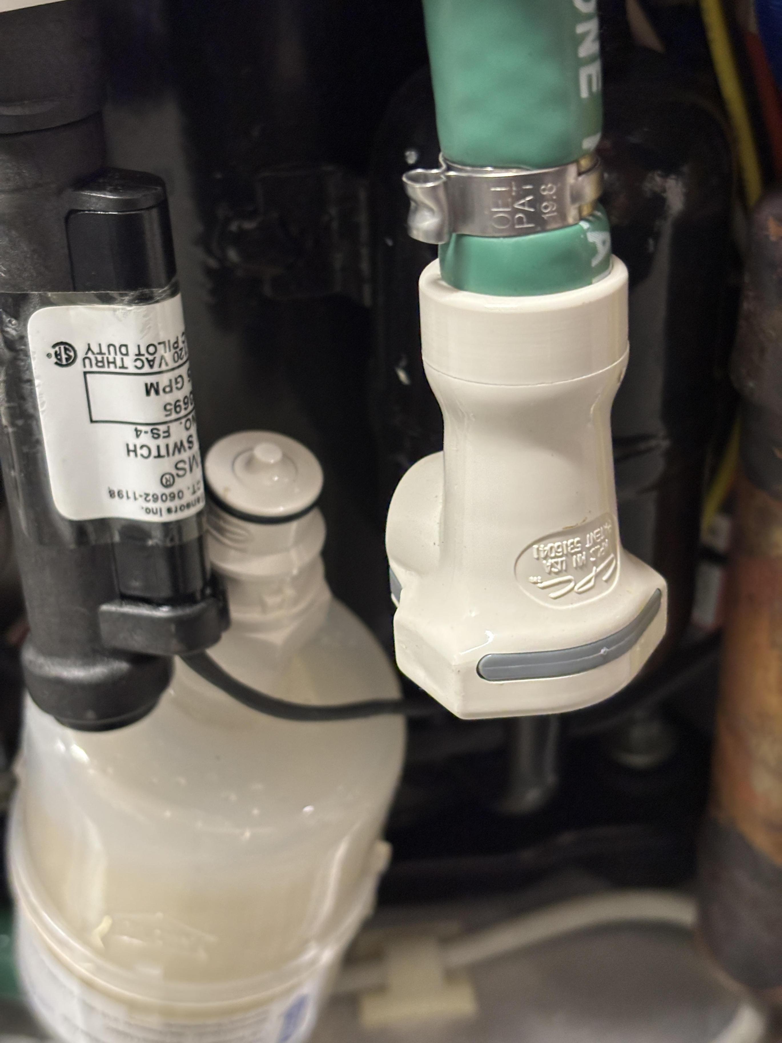
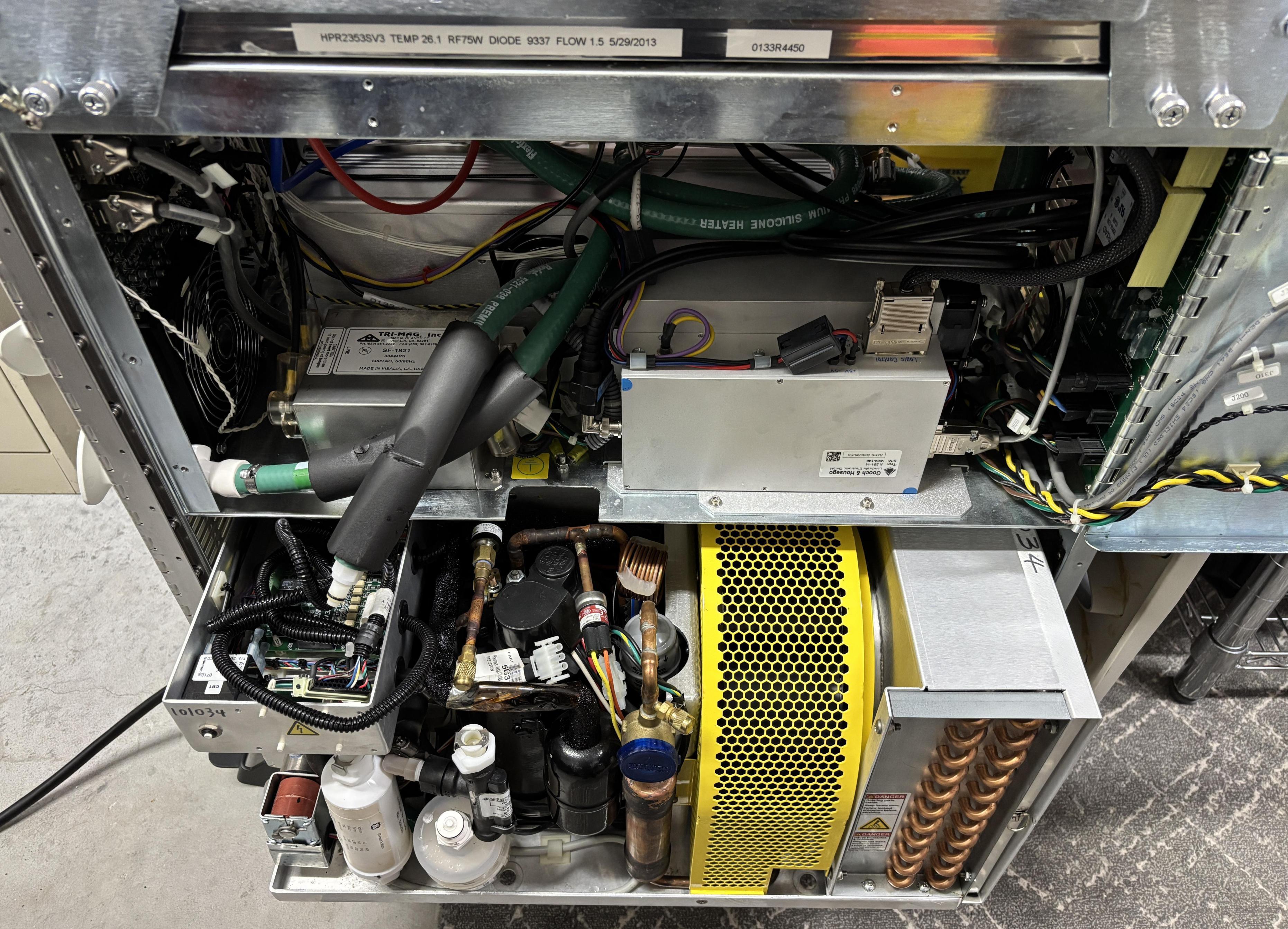
After disconnecting the water lines and electrical plugs for the chiller, removing two large hex bolts on the left side of the chiller's tray allows it to slide out from the bottom section of the frame. It can be replaced as a module or serviced outside of the remaining assembly.
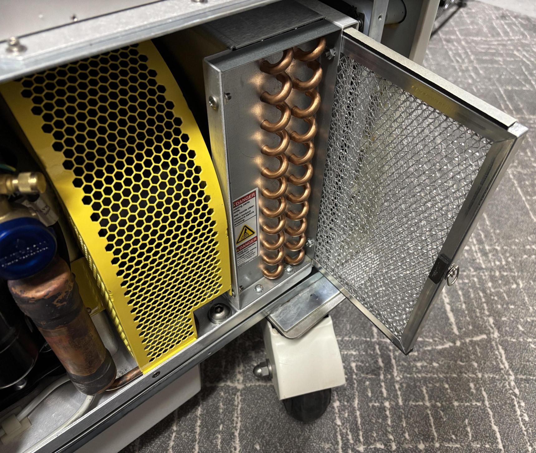
There is also a removable filter located at the front of the chiller.
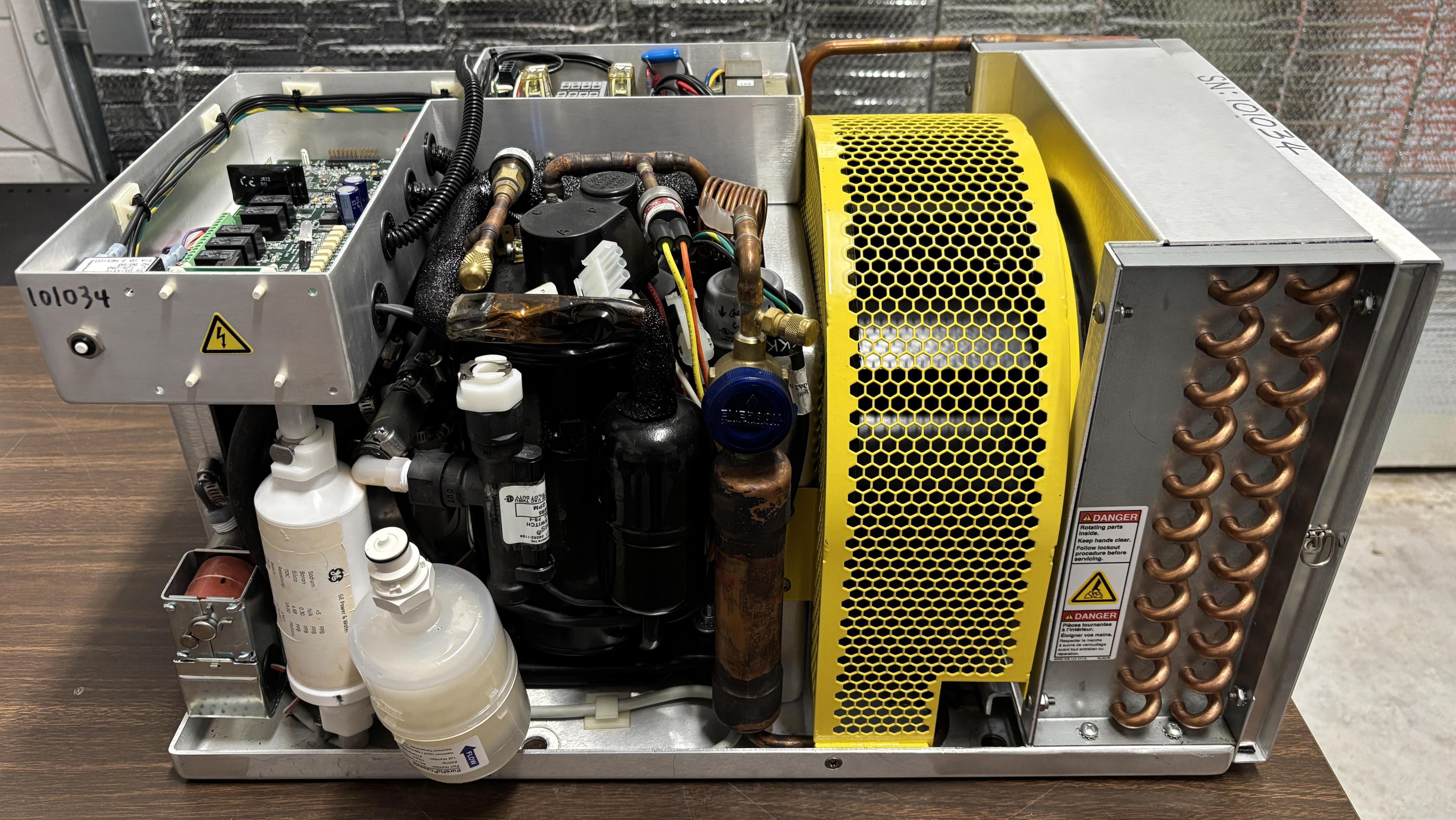
The chiller is a custom unit manufactured by Lydall Affinity and has a part number of CAA-007T-BE59CBN3 (AMS P/N: 0133-3510). It does not appear to be an off-the-shelf part and may have been designed specifically for the Greenlight laser system. Another Greenlight HPS we worked with appeared to have an older model of chiller manufactured by Lytron. The chiller cools the water that flows through the q-switch, diode baseplate, YAG rod, and diode driver to maintain their temperature. A pump (Fluid-o-Tech TMFR1) is contained within the chiller assembly to keep the water flowing. The pump is driven by a small VFD (Fluid-o-Tech TMFE1). The chiller is controlled and monitored by a dedicated control board located on top that accepts inputs from sensors and controls relay outputs to manage the system. During normal operation, the chiller periodically cycles the compressor on and off and regulates a small heater to precisely maintain the temperature of the water loop. The chiller fan runs continually while the system is powered up. The rear panel board monitors the chiller over RS-485 and controls it via a remote enable signal and one additional discrete input.
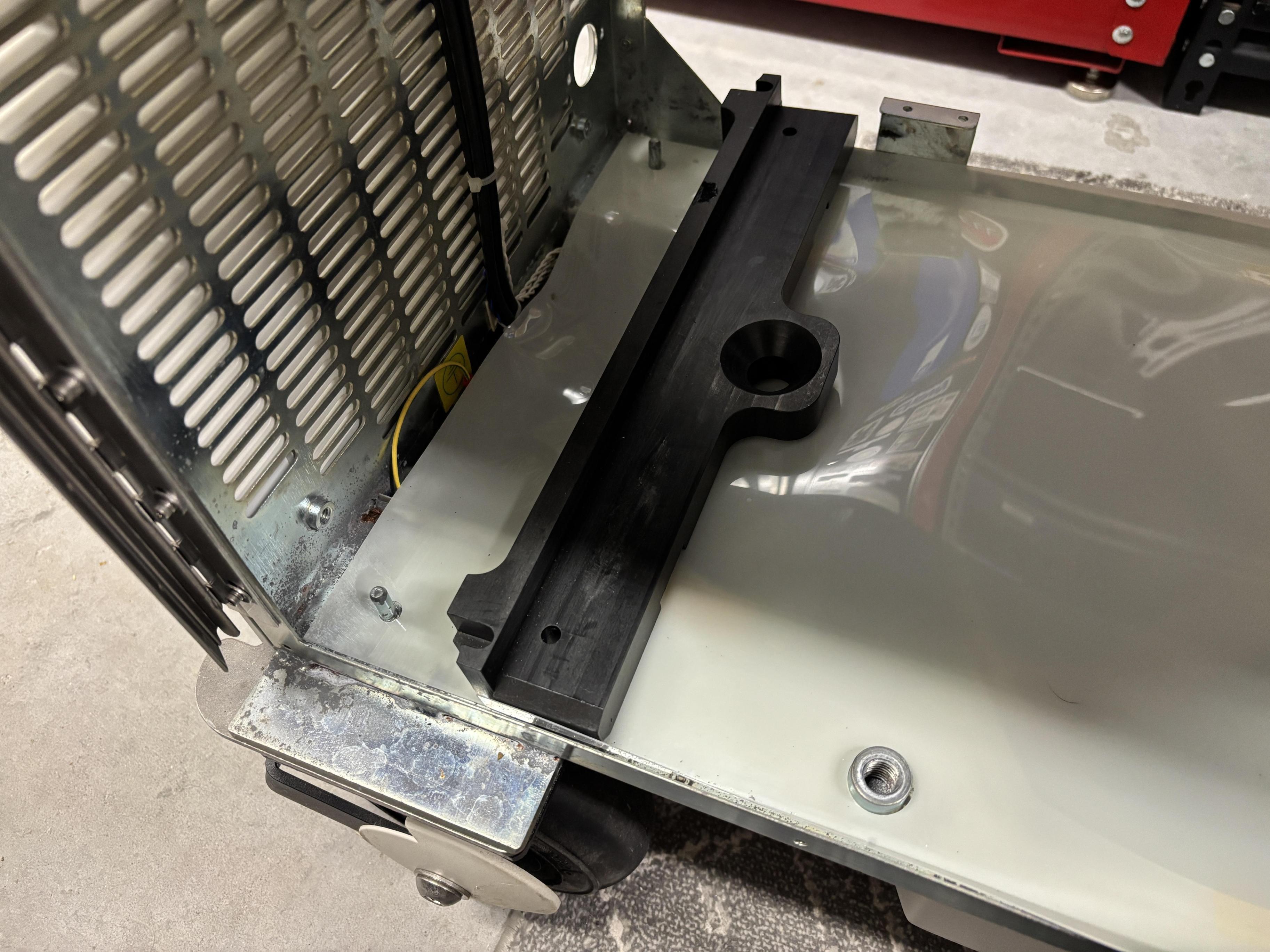
The chiller rests on two plastic guides which allow it to be slid out of the frame. One side is secured with bolts while the other has two steel tabs that hold the chiller against the floor pan.
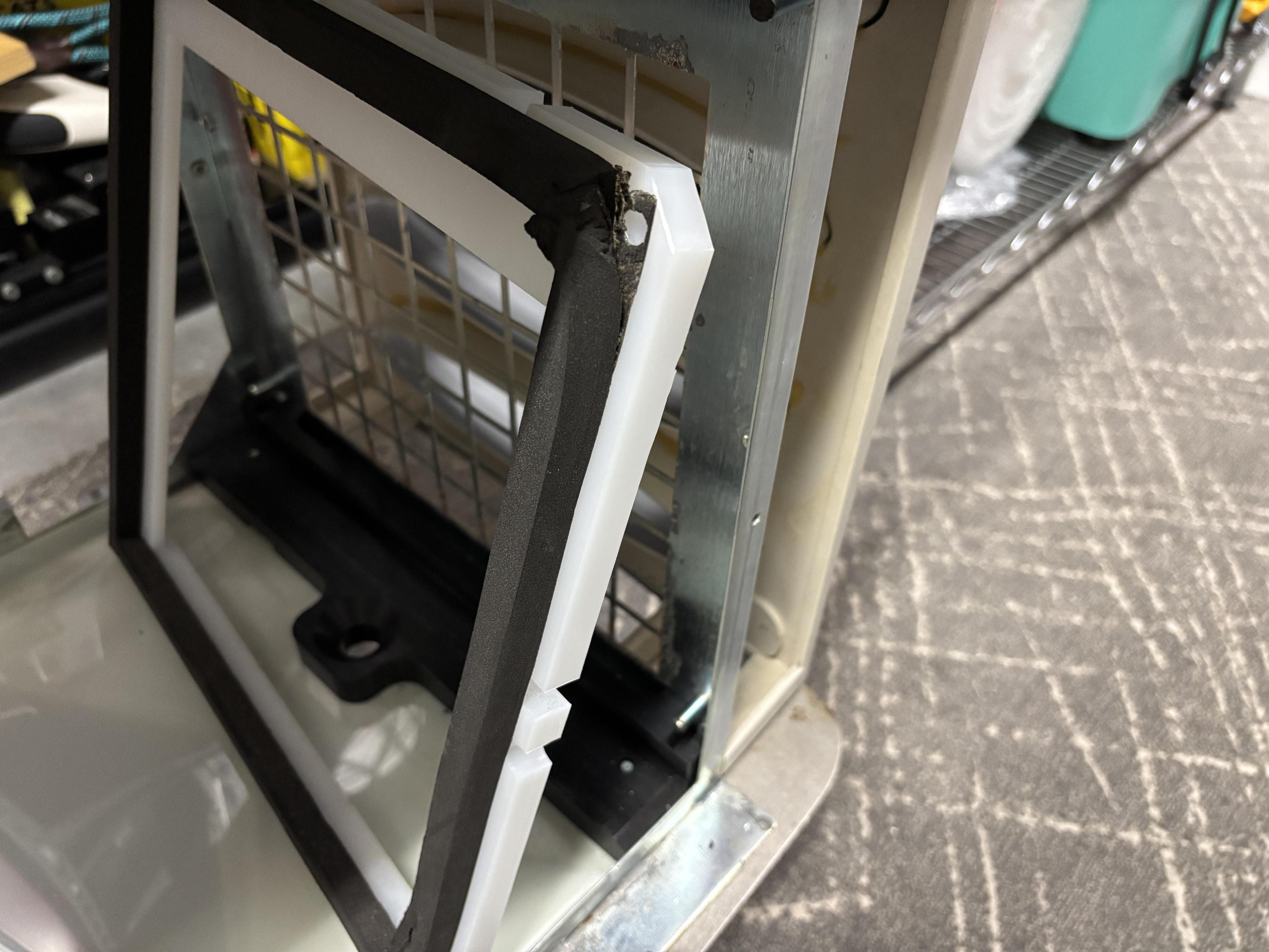
Behind the front panel is a plastic frame and gasket to keep the air flowing through the chiller's heat exchanger.
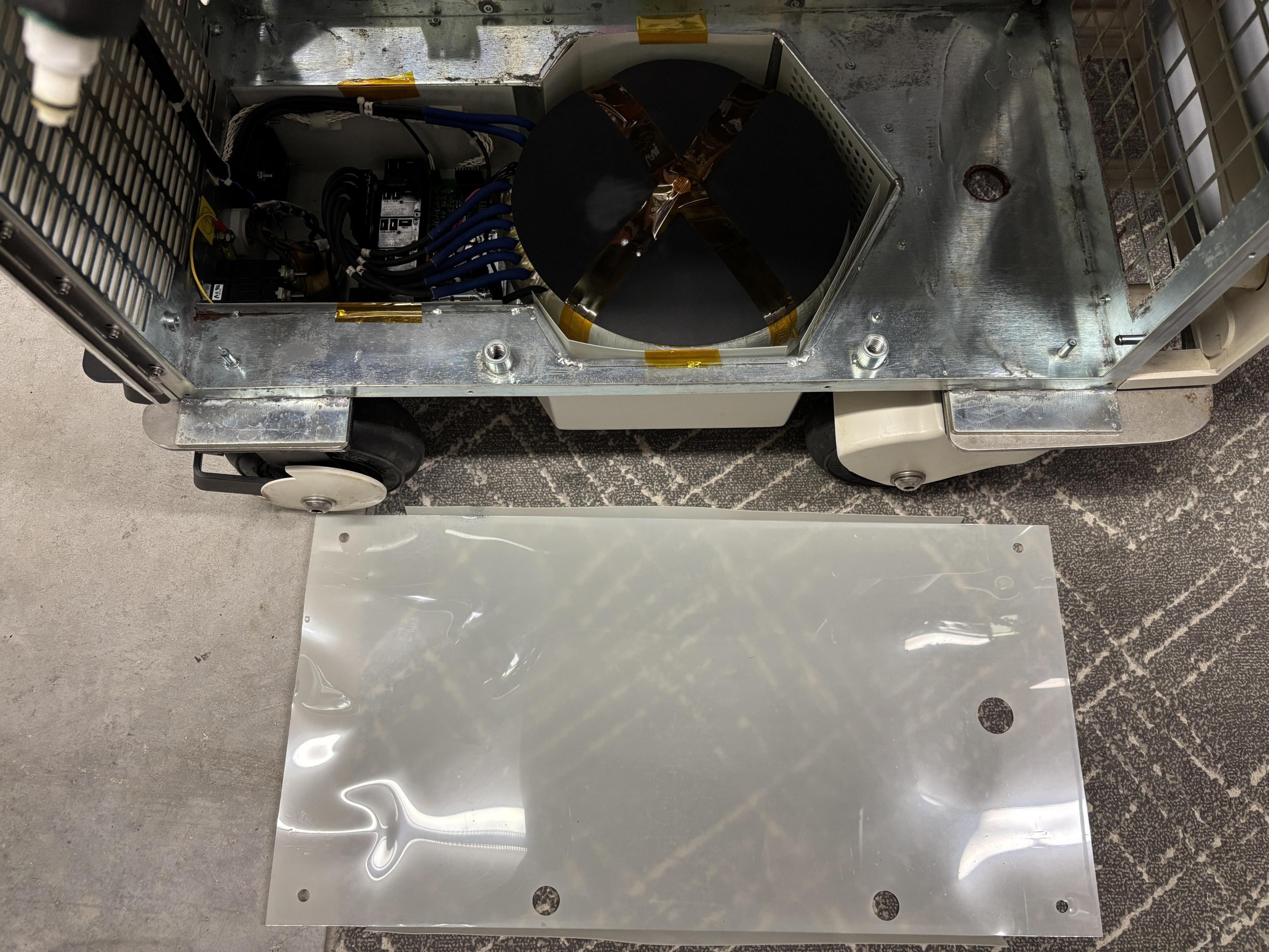
Between the steel floor pan and the chiller base is a plastic sheet, likely to prevent water from damaging the isolation transformer and electronics beneath. The chiller does not leak or drain any condensation when operating normally.
Located in a tray the extends below the floor pan and in between the casters is a large isolation transformer and the Laserscope autoselect board. The transformer has various taps which are used to compensate for different AC input voltages (208, 220, 230, etc.)
Autoselect Board and Isolation Transformer
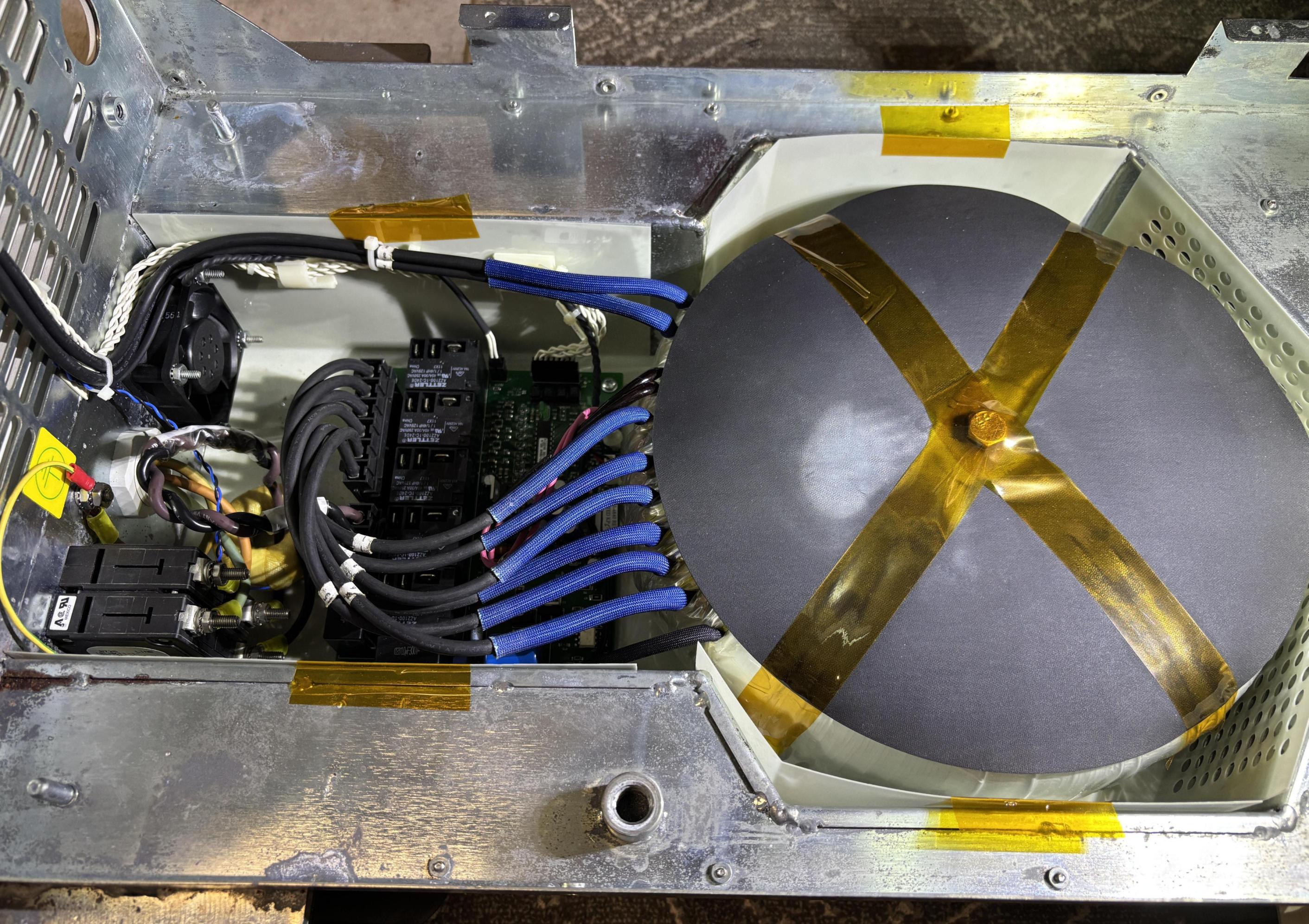
Located in this section is the autoselect board with transformer connections, circuit breaker, current transformer, AC line cord entry, and a cooling fan.
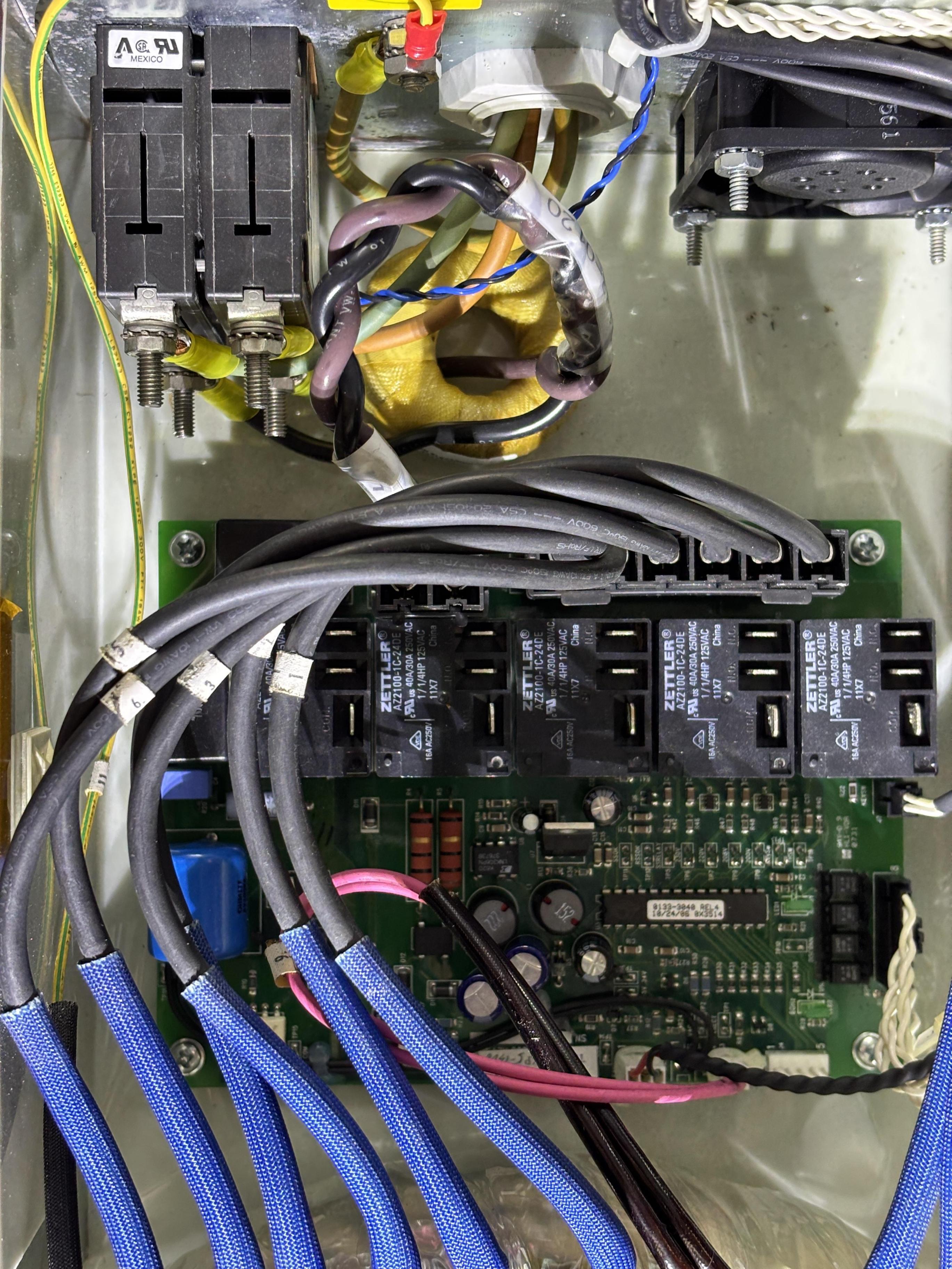
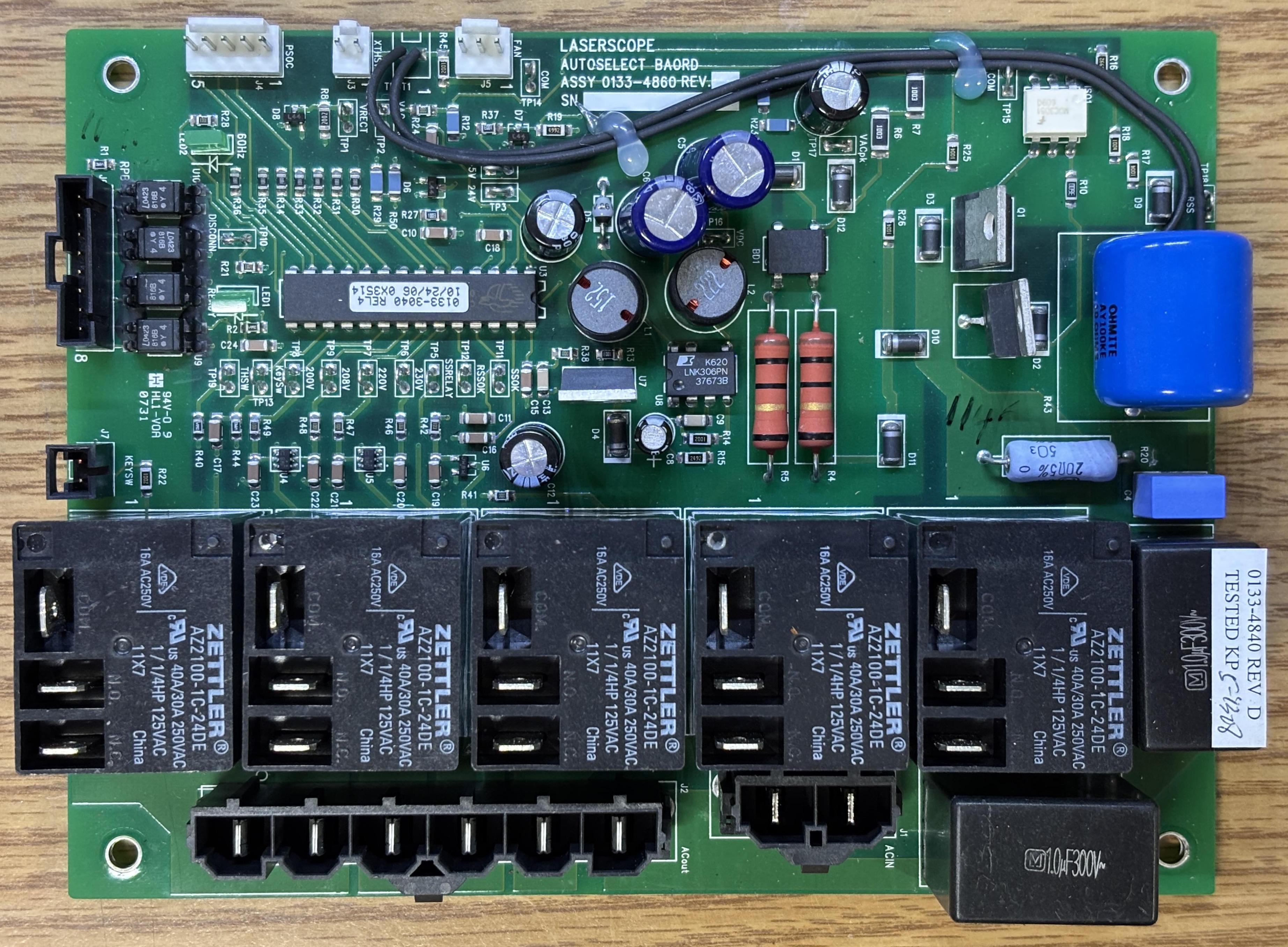
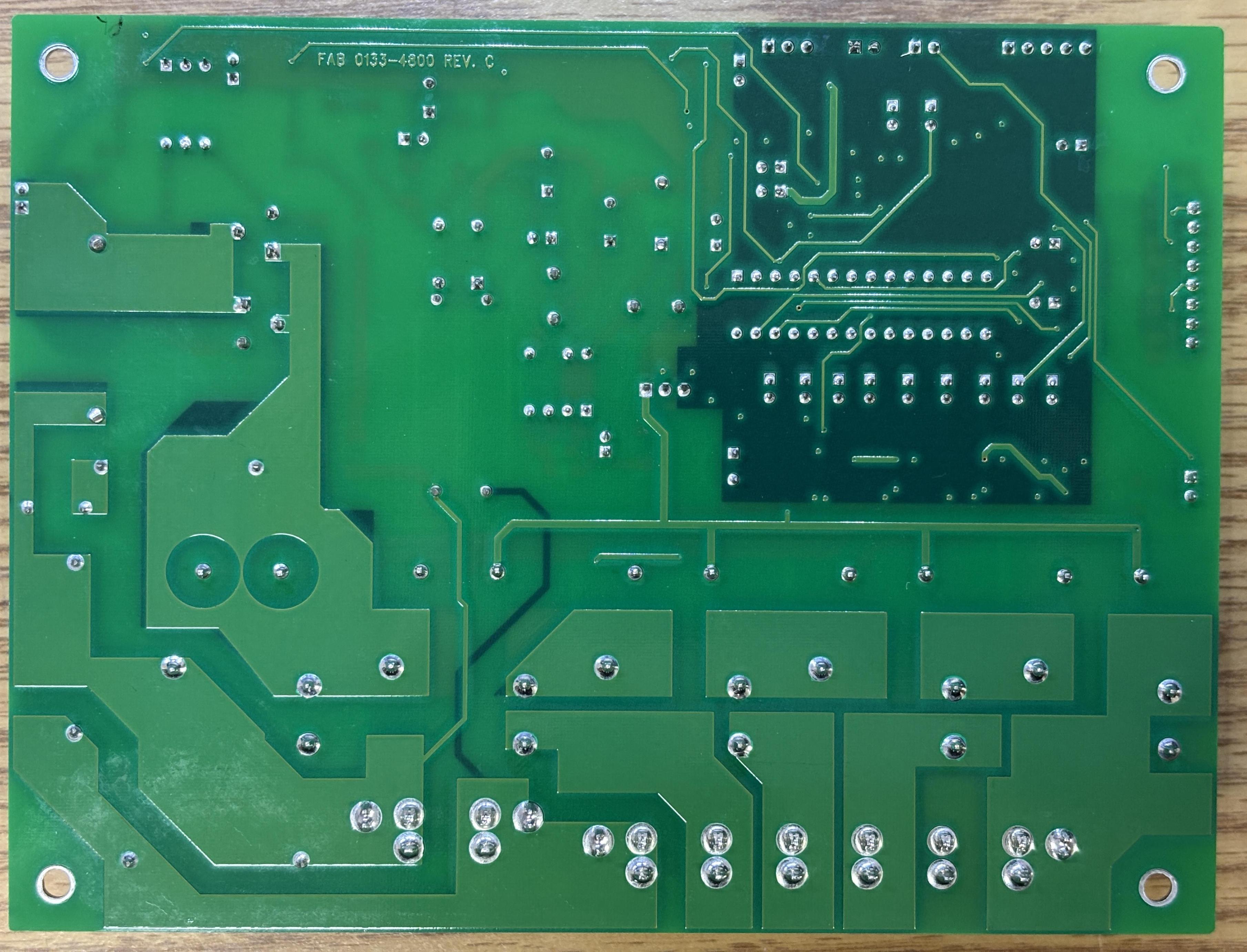
This is the Laserscope autoselect board (0133-4860). Also known as the Laserscope autoselect BAORD, as misspelled on the silkscreen. This board monitors the input AC voltage and uses the five relays to select the appropriate transformer tap in order to maintain the desired AC voltage for the rest of the system. The transformer input taps connect to relays on the autoselect board along with the AC input. The output of the transformer goes directly to the power distribution board located above the chiller. The autoselect board also has a few discrete connections, one of which routes to the front panel key-switch, and another that goes to the rear panel board. The key-switch signals the autoselect board to enable the relays and provide power to the rest of the system. When the key-switch is turned off, the autoselect board opens the relays after a short delay, cutting power to the whole system. A Cypress CY8C26443-24PXI 8-bit MCU handles these control and monitoring functions. Regarding the connector and harness that goes back to the rear panel board (RPB), it appears to have three outputs and one input (all opto-coupled). The outputs are probably for status monitoring, and we presume the input is for the RPB to command the autoselect board to do an emergency shutdown, as evident by the silkscreen that reads DISCONN. We have not yet tested this. There is a nice array of test points on the autoselect board, most of which are labeled. The large blue device is an OHMITE AY100KE PulsEater resistor. Mounted below it is a thermostat, which is connected to some pads on the board via some wires. This is a very well-designed board, as it's easy to see what's going on just by looking at it.
Rear Panel Board (RPB) [0133-0540]
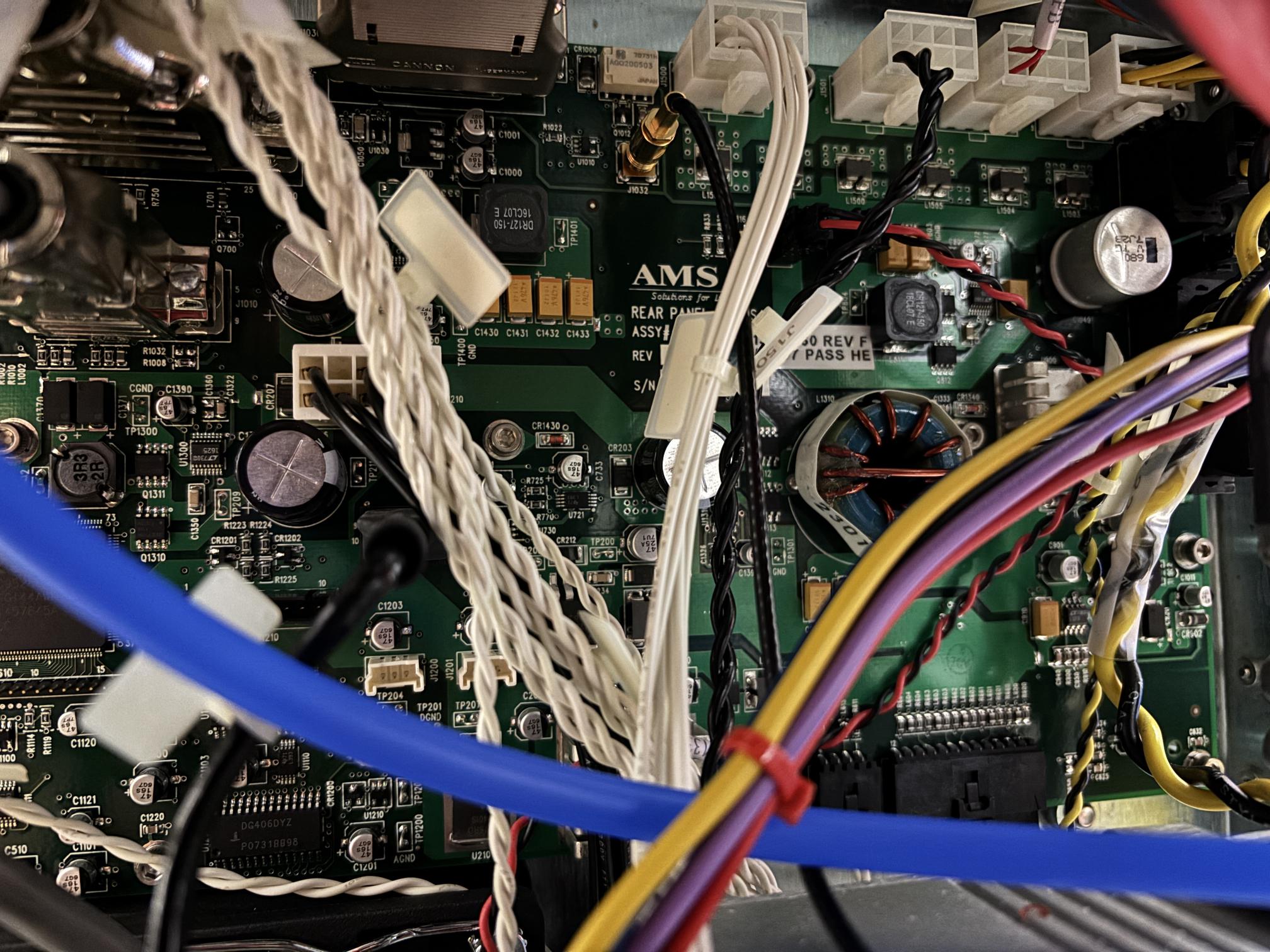
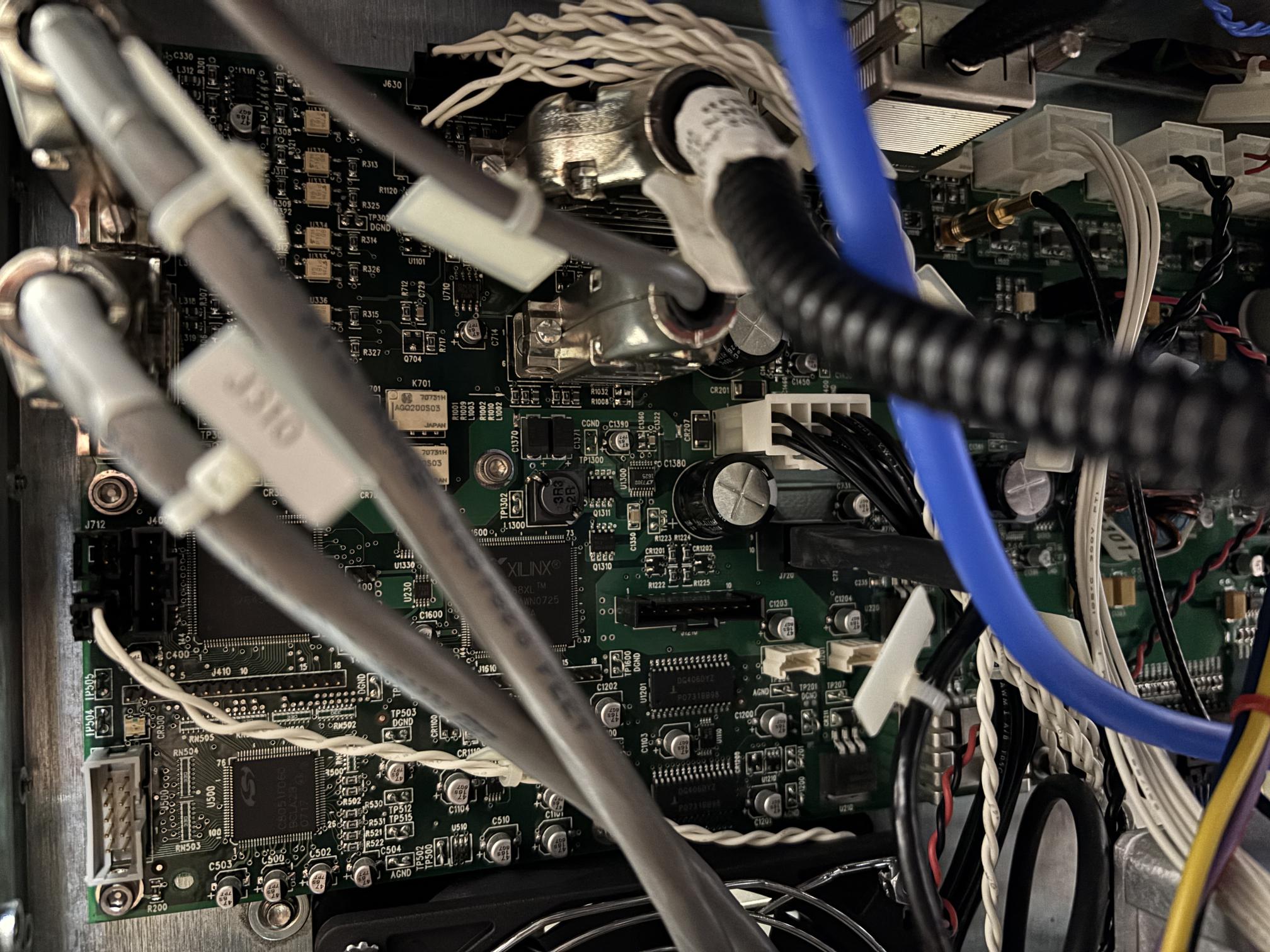
The rear panel board is the connections hub of the Greenlight HPS. It contains numerous components such as MCUs, CANBUS transceivers, RS-485 drivers, opto-isolators, relays, and discrete connections. It does appear to be the master module on the CANBUS, however, it is not the main system processor. The touchscreen board contains the primary processor. On the rear panel board are several D-SUB connectors used to interface with various parts of the system. Several discrete connections also go directly between the rear panel board and other, smaller modules such as the autoselect board, foot switch, E-STOP button, thermostats, and flow switches. The rear panel board communicates over CANBUS and RS-485 with the DLB, touchscreen, diode driver, and resonator. It has a direct RS-485 connection to the chiller. It has direct connections to the AOM (Q-switch) driver and is powered directly by connections from the power distribution board as well as the low-voltage power supply (24V DC). This board distributes DC power to the touchscreen, fans, resonator board, and DLB. Also on the rear panel board are multiple XILINX XC95288XL CPLDs and Silicon Labs C8051F060 MCUs. These components and related connections are replicated on several other modules within the system.
Acousto-Optic Modulator (AOM) / Q-Switch [0133-2010]
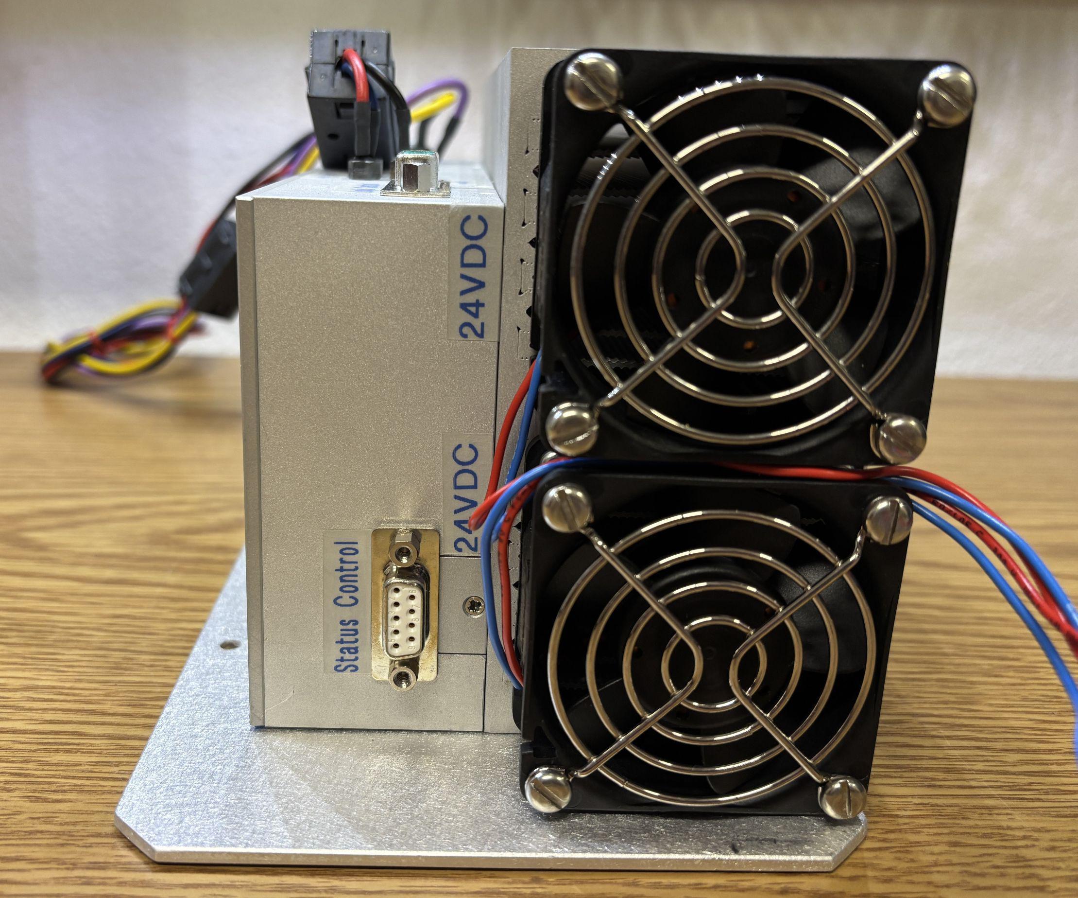
This device generates the RF energy to drive the q-switch crystals located within the resonator and pulse the laser. This pulsing allows for higher laser output power levels and modulation of the beam. According to the XPS service manual, the successor to the Greenlight HPS, the q-switch repetition rate is 15-22kHz in vaporization mode and 12Hz, 25% duty cycle in coagulation mode. Since the driver is DC powered, all connections route to the rear panel board. Additional connections include a D-SUB connector with two coax terminals labeled "logic control", and a 9-pin D-SUB connector labeled "status control". Older HPS models will have a Landwehr branded q-switch driver while newer models will have one branded Gooch & Housego and Landwehr.
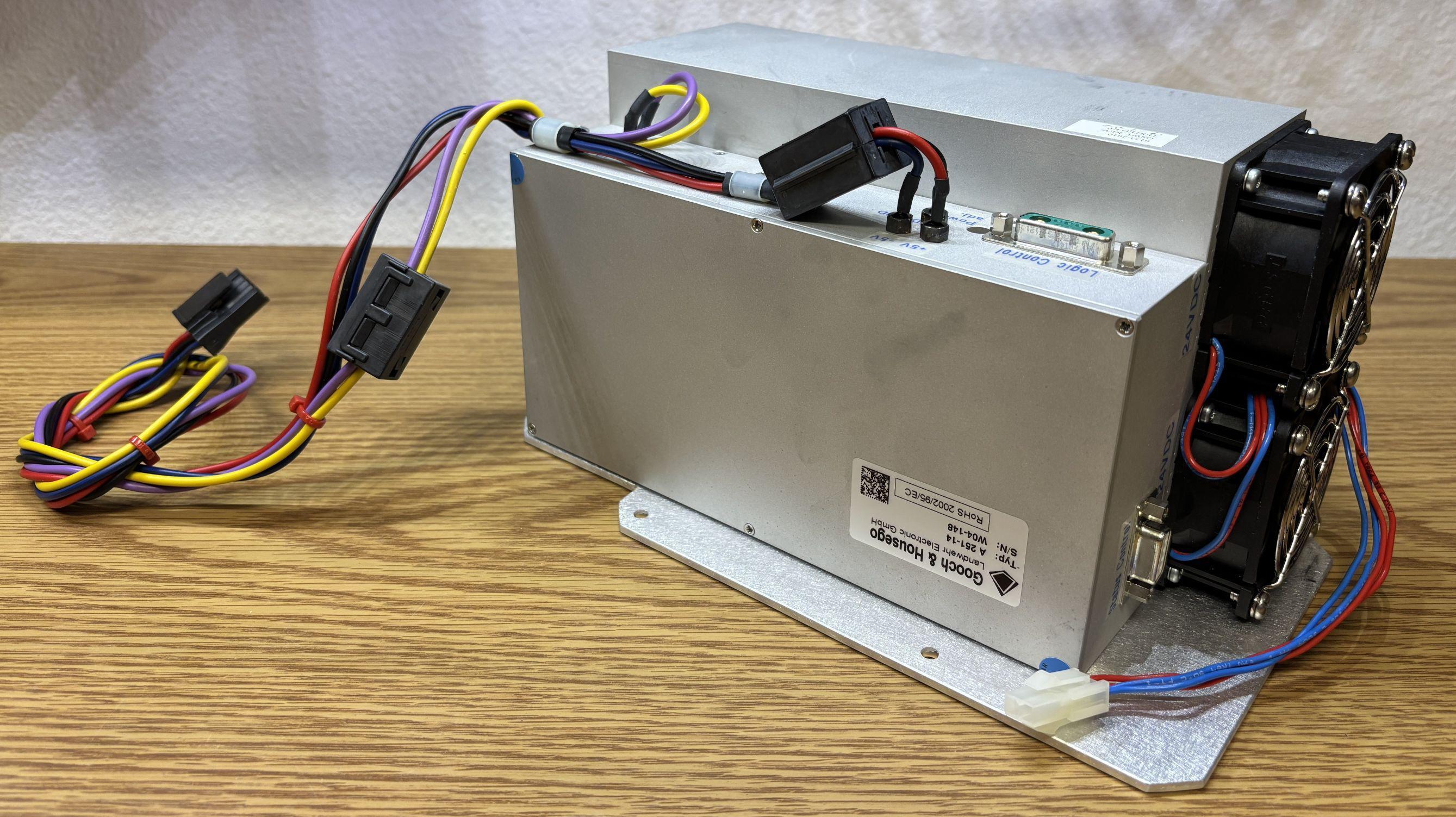
The q-switch driver is air cooled and uses a BNC connection for the RF output to the crystals. A sticker on the side of the resonator leads us to believe that the crystals are pumped with around 75 watts of RF energy.
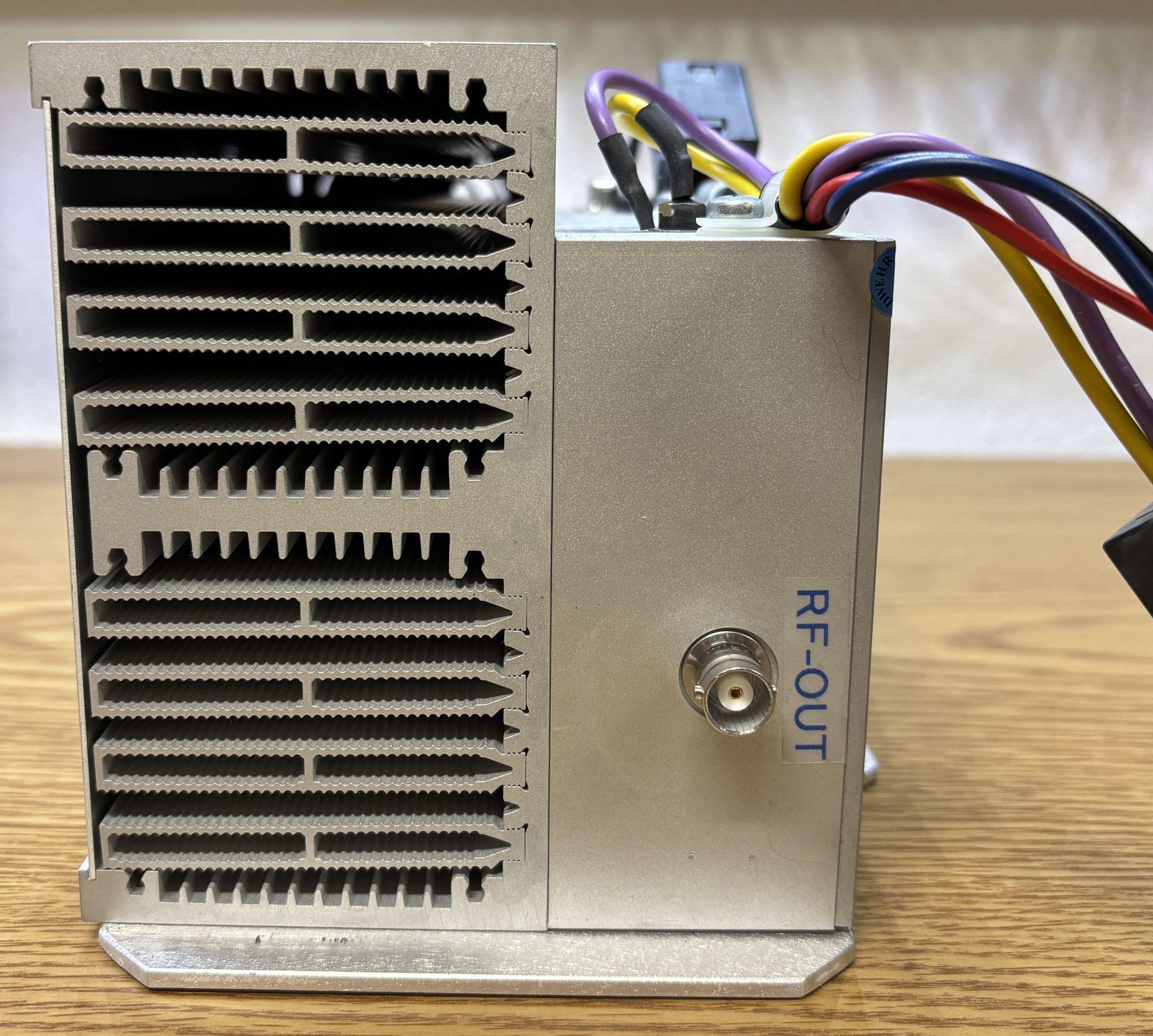
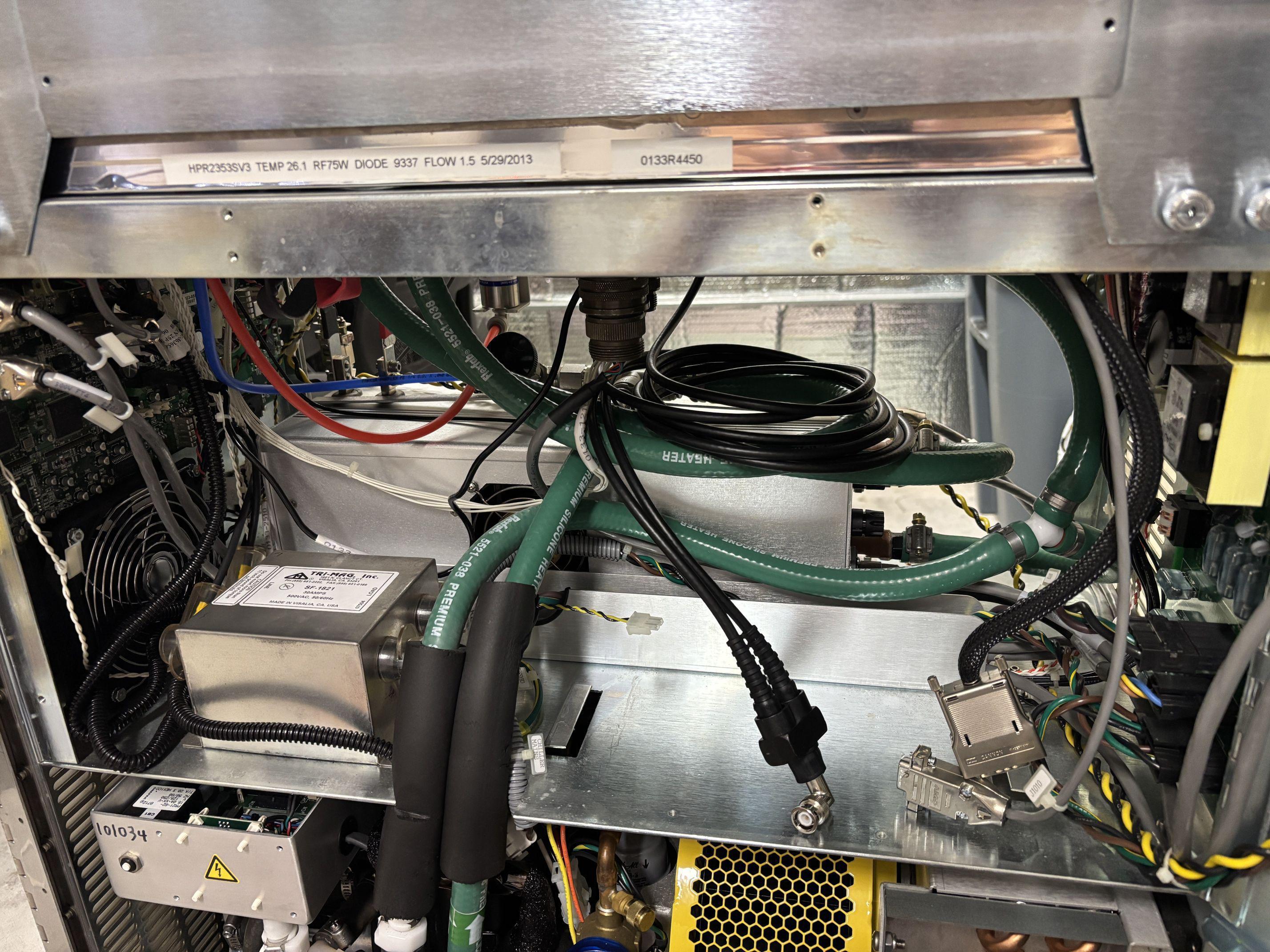
With the q-switch removed, more components are visible, such as the dual-core coaxial cable which connects the q-switch driver to the crystals. Additionally, there is a small Molex connector for the q-switch driver fans.
Power Distribution Board (PDB) [0133-0640]
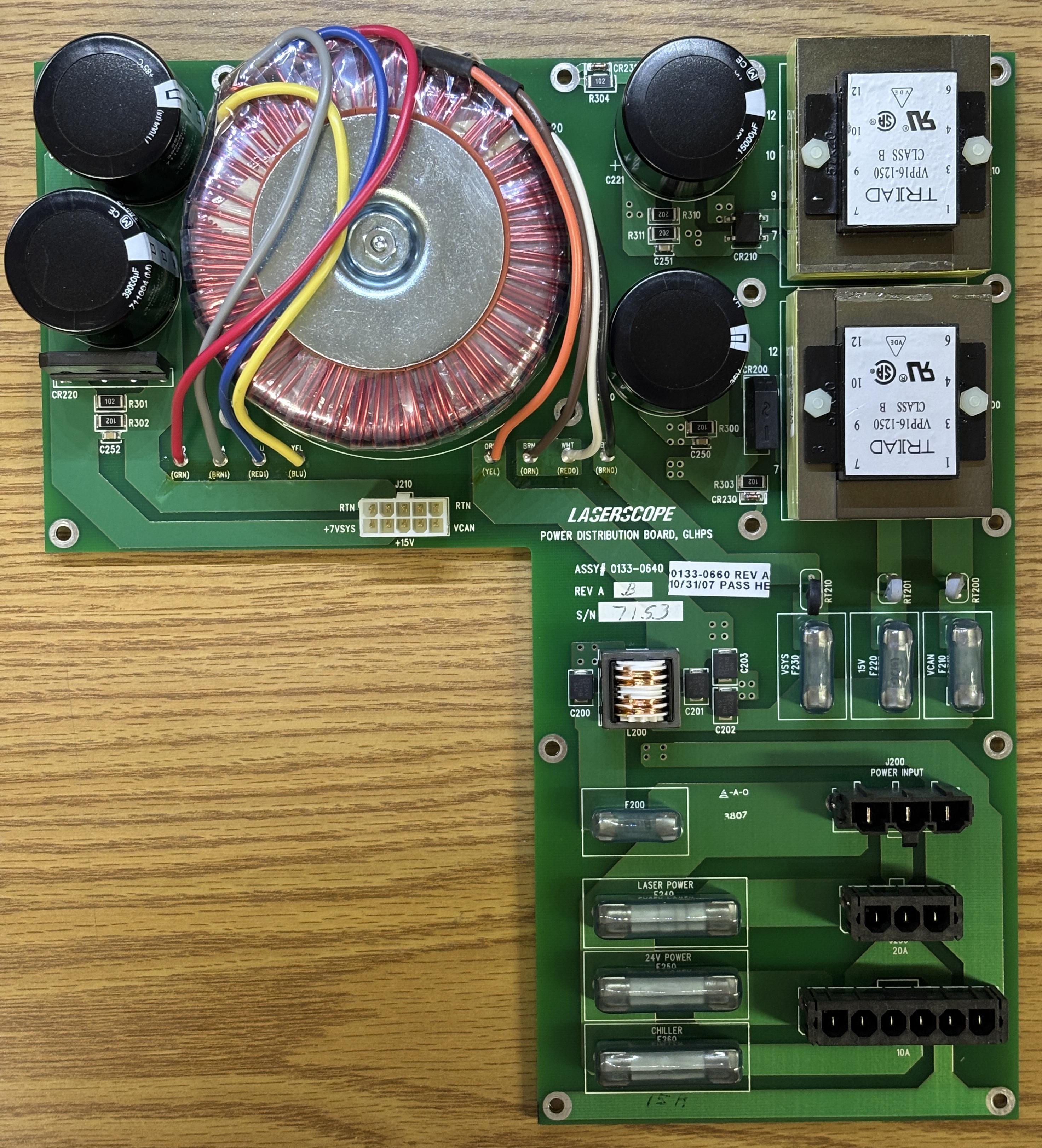
The power distribution board is responsible for breaking out the AC input to other modules within the system. Some are AC-powered and fed directly such as the diode driver and chiller, while others are DC-powered. The DC powered components are fed through the rear panel board. One harness between the rear panel board and power distribution board is used to transfer DC power between the boards, before and after conversion. There are multiple transformers, including a toroidal transformer, attached to the power distribution board. The 24V DC voltage is further converted by this board to 15V DC and 7V DC. There are several fuses that protect each module/connection.
VueMetrix Laser Diode Driver (LPS) [1000-0360]
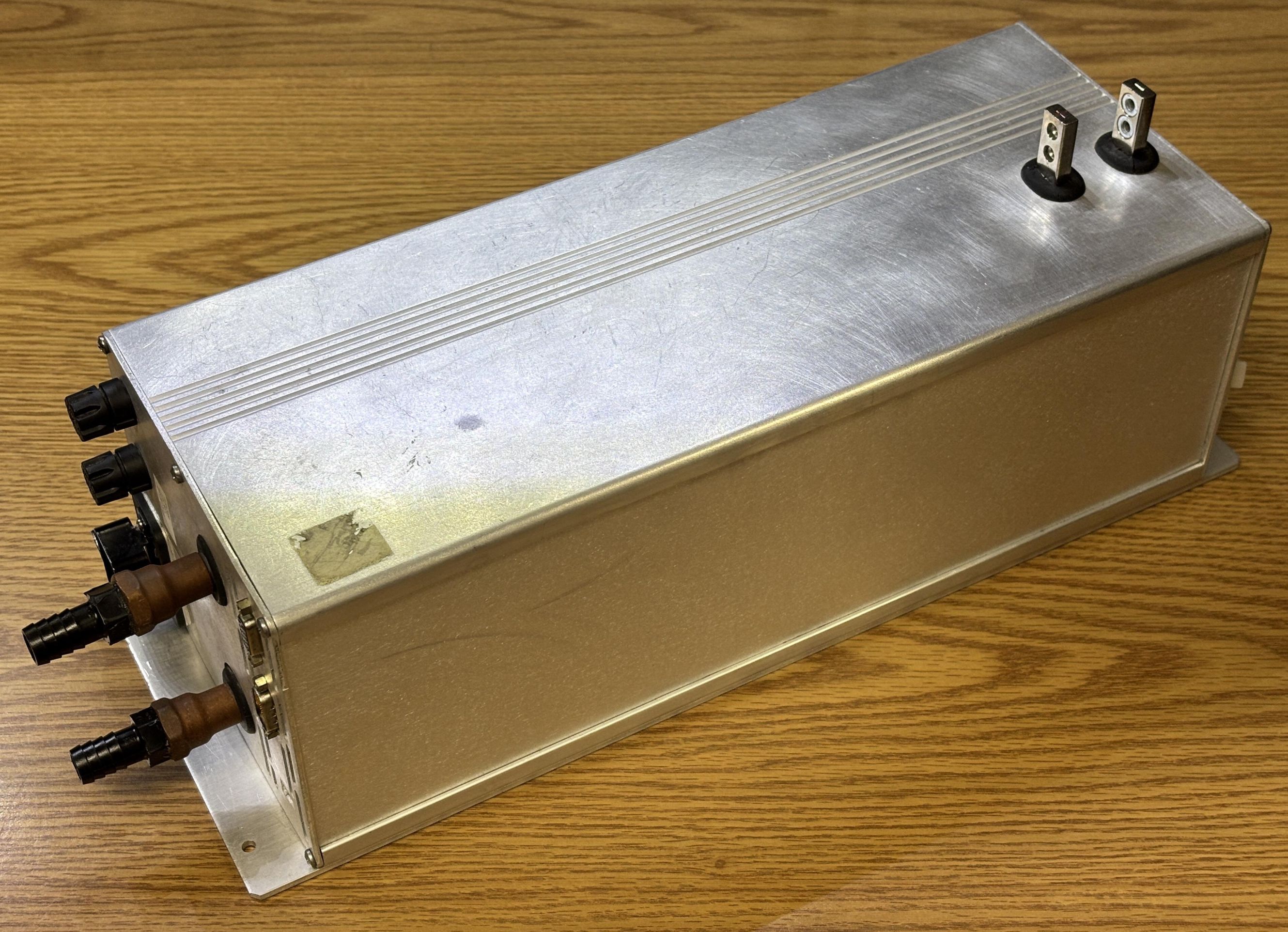
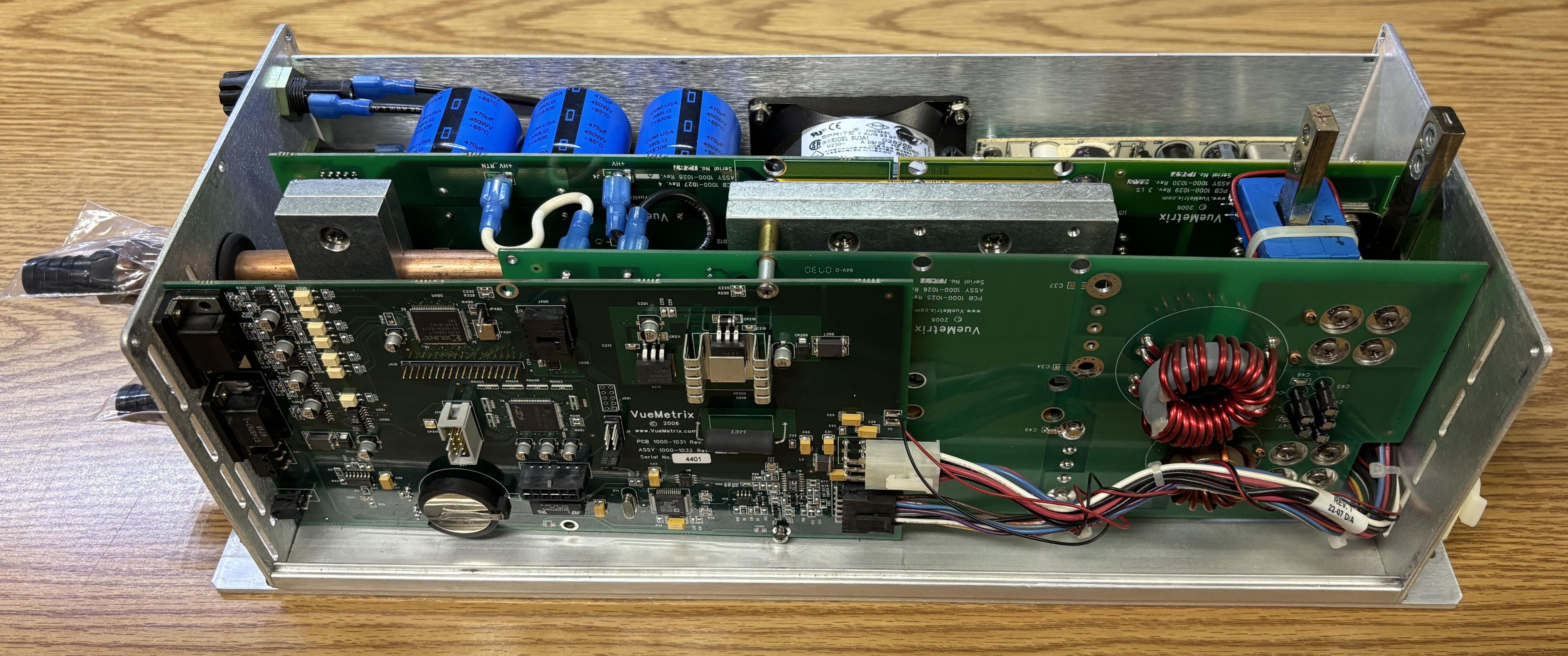
This is the diode stack driver. It's a custom component manufactured by VueMetrix for the Greenlight HPS, and is likely based off of their Vue-HV laser diode stack controller. This monster of a controller drives an 808nm diode stack capable of producing over 200 watts of laser light, which is used as the pump source for the 532nm DPSS laser head (resonator) within the Greenlight HPS. The large studs on top are the connection to the laser diode stack. They are designed to carry hundreds of amps of DC current, at a maximum voltage of around 15 volts. The diode driver contains a rectifier, and two DC-DC converters, which are water cooled. The two copper pipes and barbs are used for the cooling loop that includes other components as well. The diode driver does have a small fan, but that is only for the control electronics and its internal low-voltage power supply.
For the AC input, it uses a 30-amp IEC connector which is occupied by a plug that routes back to the power distribution board. For digital control, there are two DB-15 connectors, one male and one female. These carry both CANBUS and RS-485 data and form the connections for the digital control loop that includes other components such as the data logging board and rear panel board. The small 2-pin Molex connector below the DB-15 connectors is a discrete interlock connection.
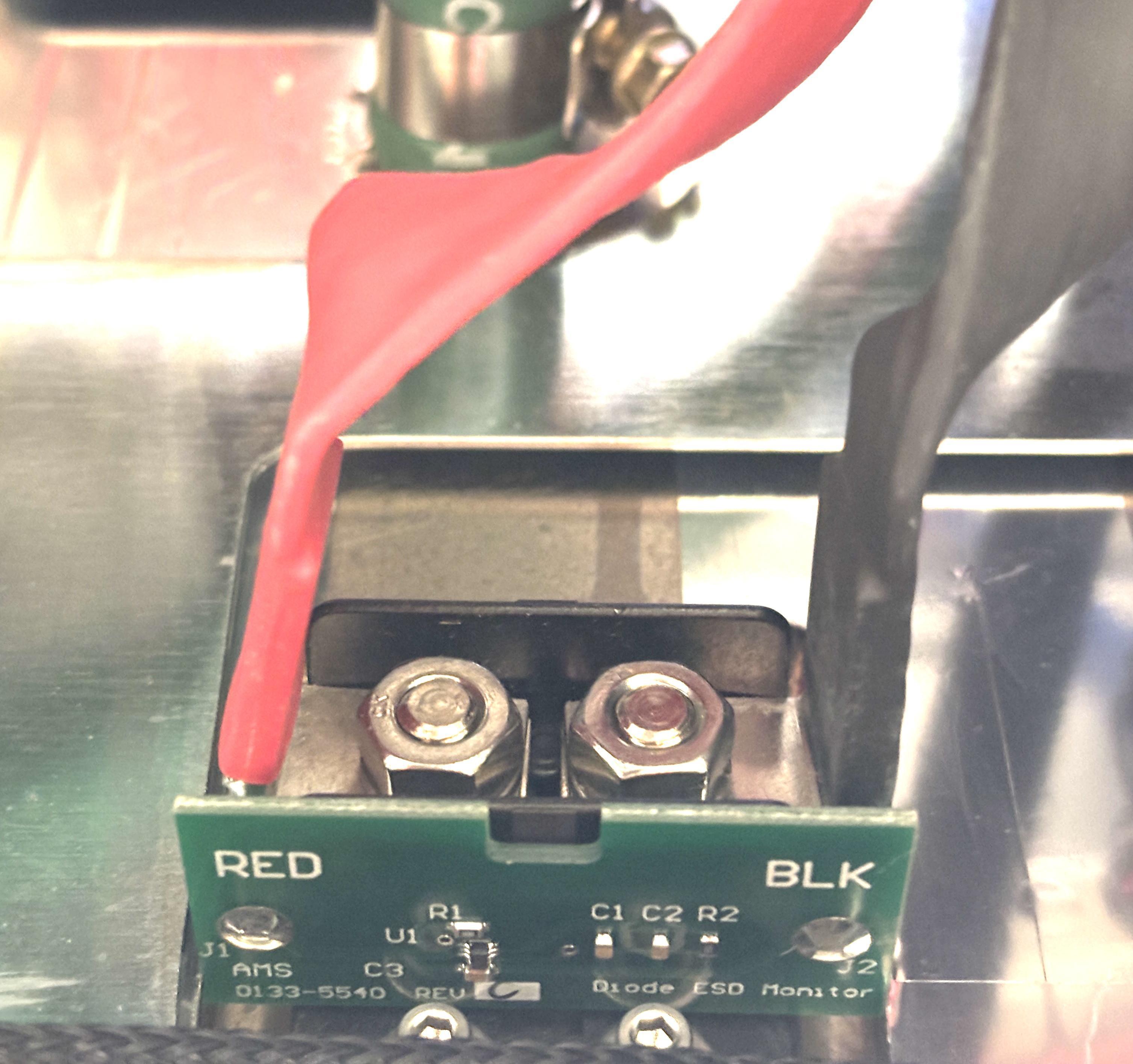
The braided cables are secured to two studs located on the underside of the resonator assembly. There is also an ESD monitor board attached to these terminals. There aren't any other connections to the board, so it's likely used as a forensic device to determine if the diode has been exposed to electrostatic discharges.
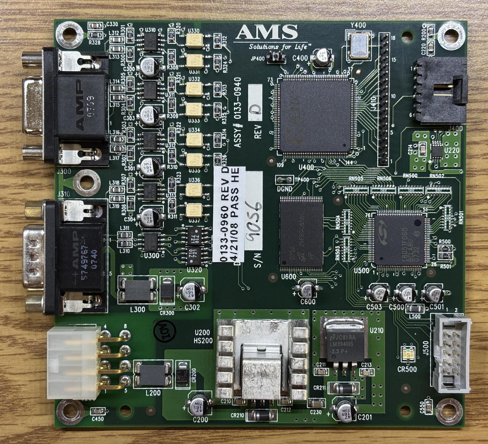
Data Logging Board (DLB) [0133-0940]
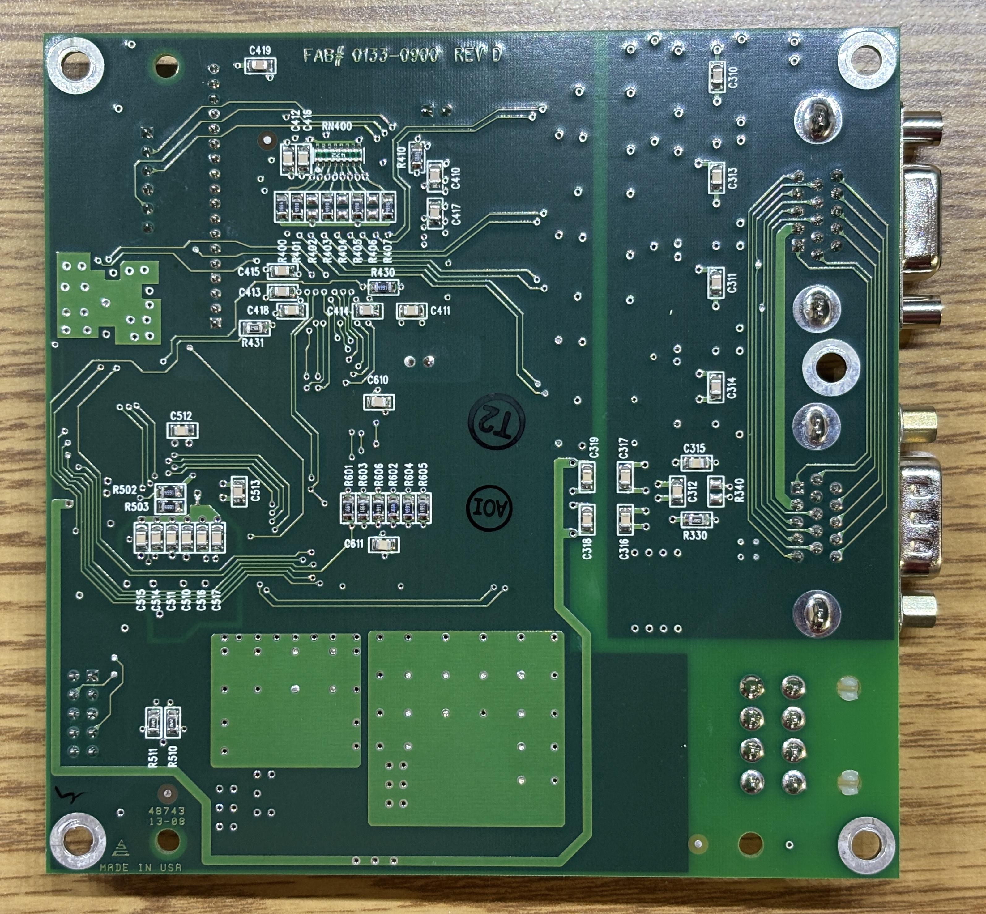
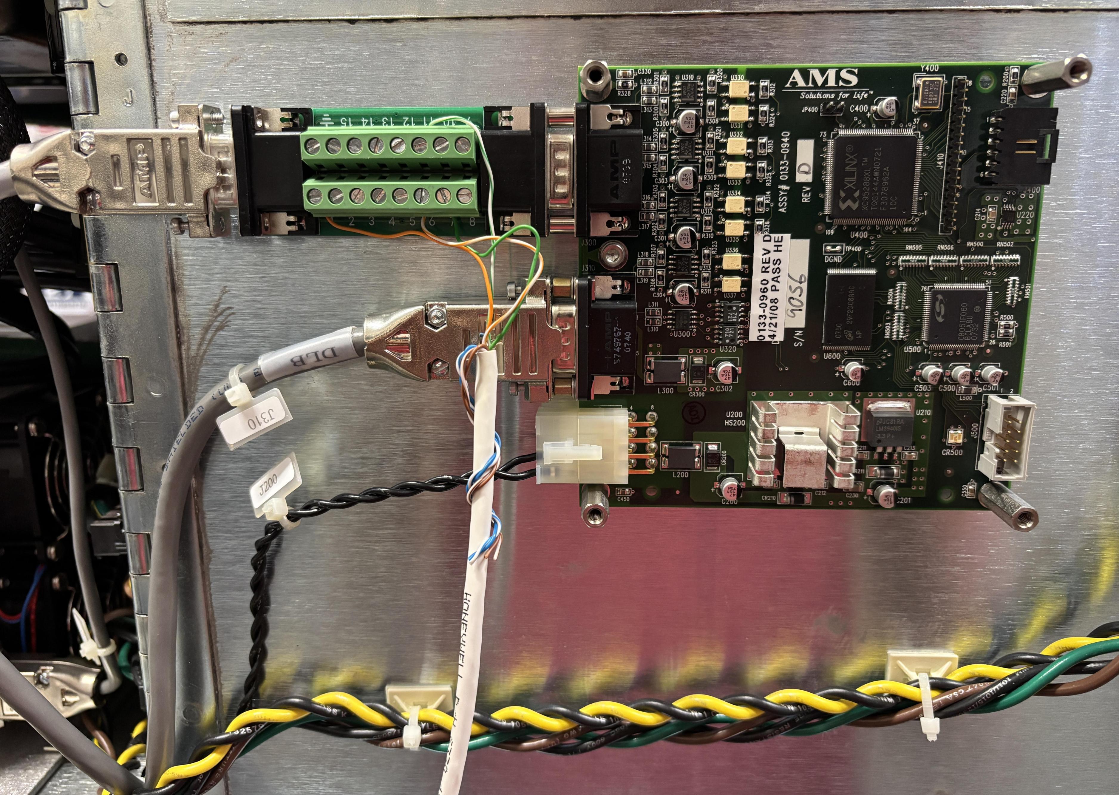
We call this the "medical malpractice" board. It's basically a black box that logs all system activity from startup to shutdown. The board has the same RS-485 and CANBUS interface arrangement as the other modules (diode driver and rear panel board). It also features the same Silicon Labs C8051F060 MCU and XILINX XC95288XL CPLD. Most notably, it has a Micron MT29F2G 2GB NAND flash chip, where is where all this data gets stored. This board participates on the CANBUS network mostly as a passive listener, it responds to periodic polls and disconnecting it causes an immediate system shutdown. It is likely that this board is used for diagnostics and would be a critical piece of an investigation into a safety issue related to the device. Presumably, there is some proprietary method AMS would use to read data out of this board, even when removed from the system. We are unsure if the data is encrypted in any way. The data logging board has two DB-15 connectors. J300 goes to the resonator board, and J310 goes to the rear panel board. During analysis and CANBUS data capture, we noticed the diode driver's calibration table being transmitted to the DLB during the initial system startup period.
User Interface Touchscreen (DISP) [0133-0340]
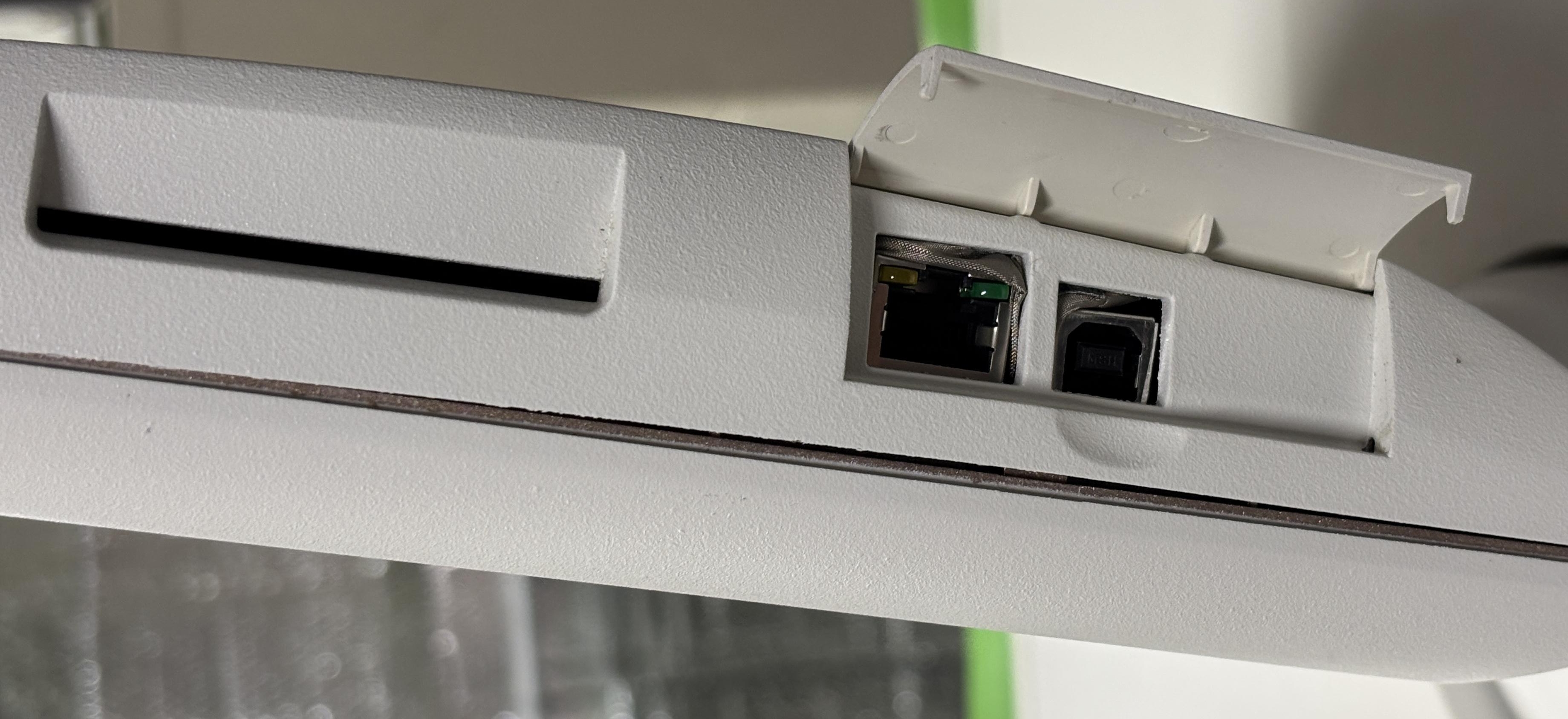
The primary user interface for the Greenlight HPS is based around a small touchscreen display mounted on top of the unit. The display can be rotated, tilted, and stowed against the top case with the screen facing down to protect it during transport. Other than the breaker, key-switch, e-stop button, and foot switch, there are no other buttons or physical controls on the Laserscope. All functions and parameters are selected or adjusted using the touchscreen. It appears to be a resistive touchscreen and may be partially damaged on our unit as it sometimes senses touch input when nothing is pressing on the screen. It also does not respond to any legitimate touch inputs. There is a small speaker built into the display. An audible tick can be heard when touching the screen. This tick can be heard repeatedly at times when the touchscreen is malfunctioning. Additionally, when the system finishes the startup sequence and displays the home screen, a female voice announces "STANDBY". The same voice announces other laser states such as "READY" and "COAG" when coagulation is active. Located on the side of the display is a smart card slot for the fiber access card. Below that is an Ethernet port and a USB port which are normally covered by a plastic door. The USB port identifies as a USB-to-serial converter when connected to a computer, but we observed no data from it and the system did not respond to any commands that we sent it. The Ethernet port also did not establish a link at any time during our testing. These are likely for diagnostics and service only. The XPS manual specifically refers to the USB port as entry point for service mode.
Removing four small hex screws located under rubber plugs allows the front of the display to pull away from the rear casing. This reveals the internal components. The inside of the plastic casing appears to be coated with a metallic material, likely to minimize EMI.
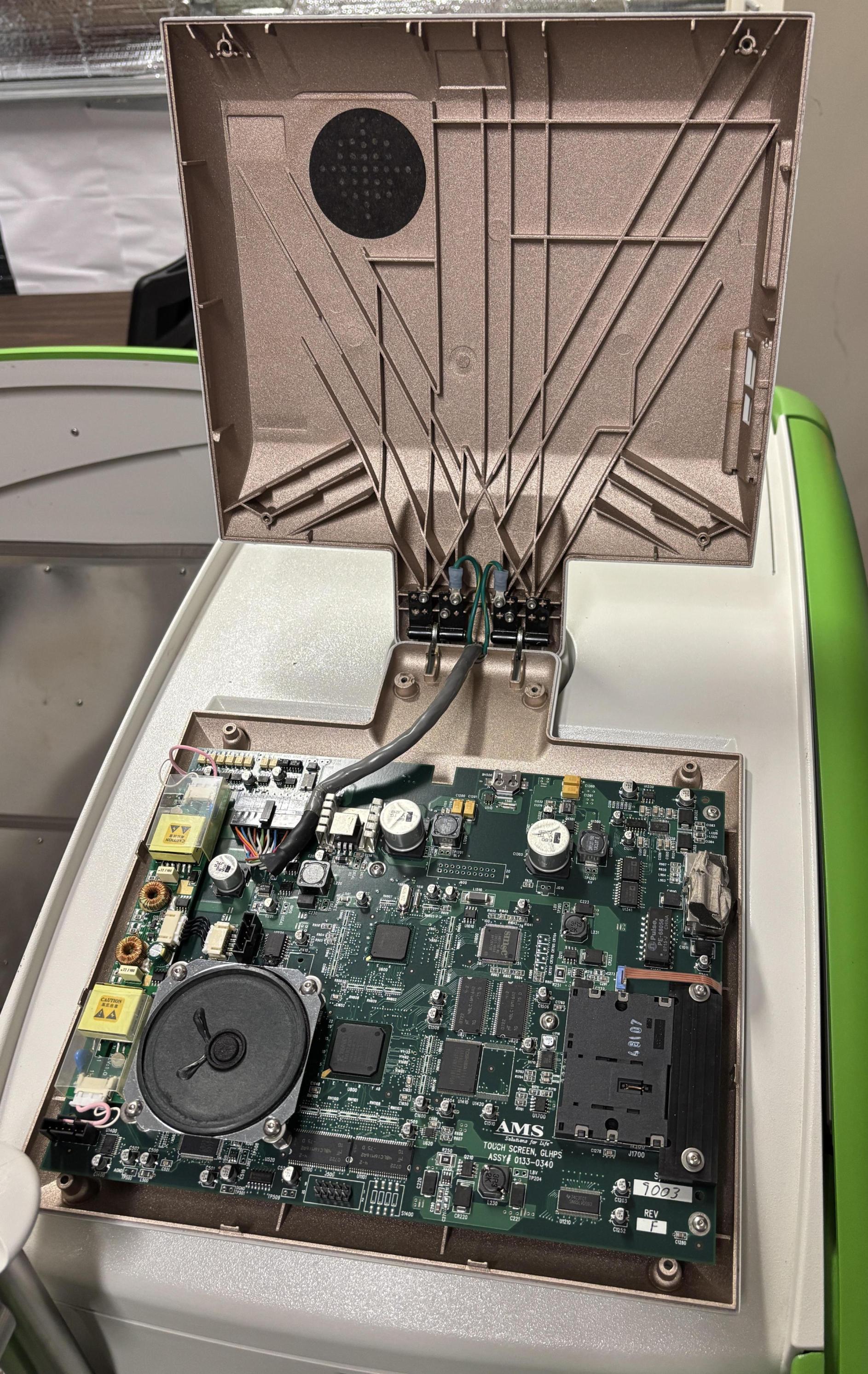
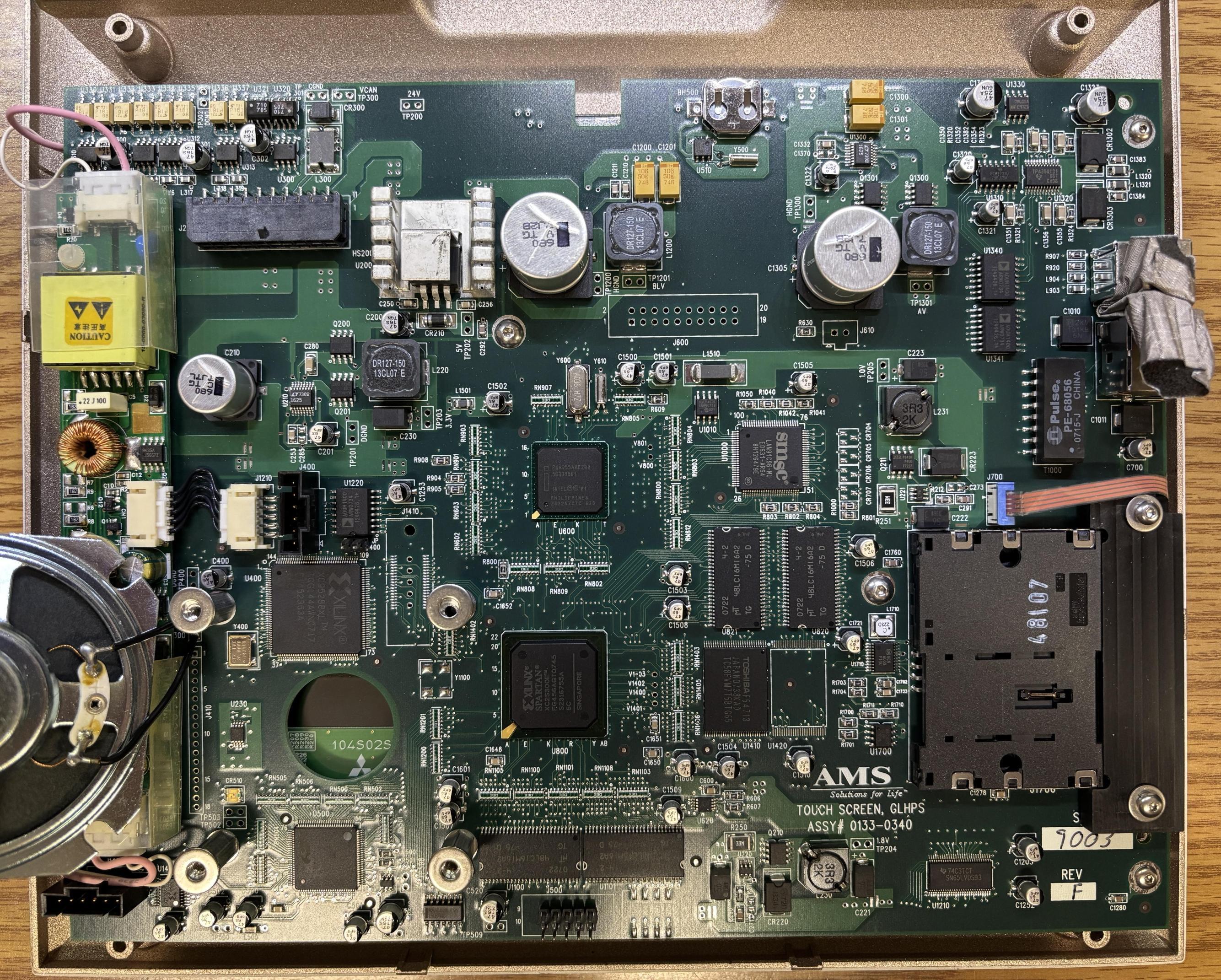
This display board is quite complex, and is centered around an Intel PXA255 in addition to the same replicated logic as the other components. The display screen is also a CANBUS participant and features the same RS-485 connections as the other major modules. The touch screen board plays an integral role in monitoring and sequencing all the other components during startup and laser emission. Also on the board is the speaker, backlight inverter, smartcard reader, and a small battery.
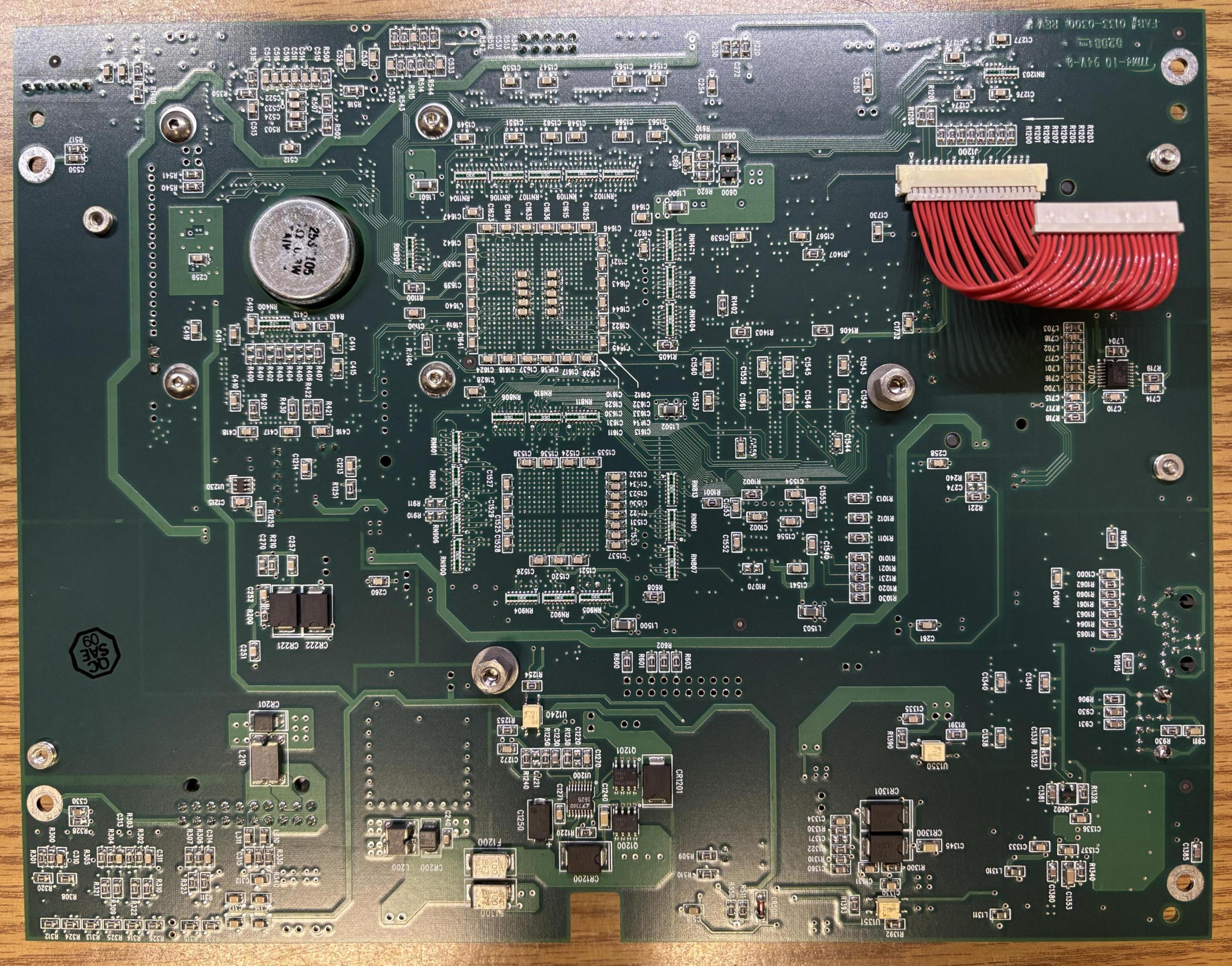
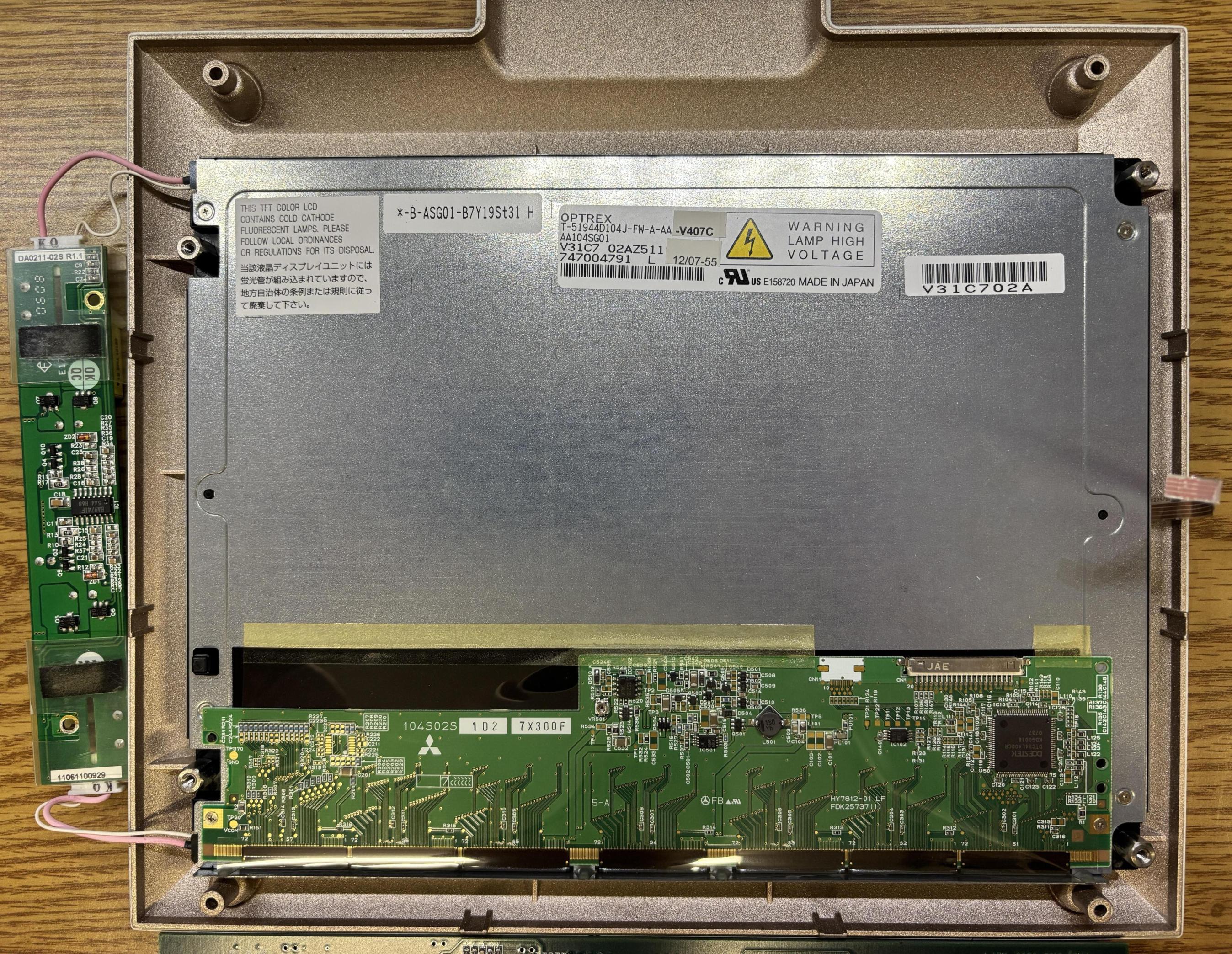
The actual LCD display panel is manufactured by OPTREX and has a part number of T-51944D104J-FW-A-AA. There is a Mitsubishi logo on the circuit board attached to the bottom of the display panel.
Top Cover
The top cover, which includes the storage trays and touchscreen, can be removed after loosening 12 spring-loaded thumbscrews. Three on each corner, then it lifts straight up.
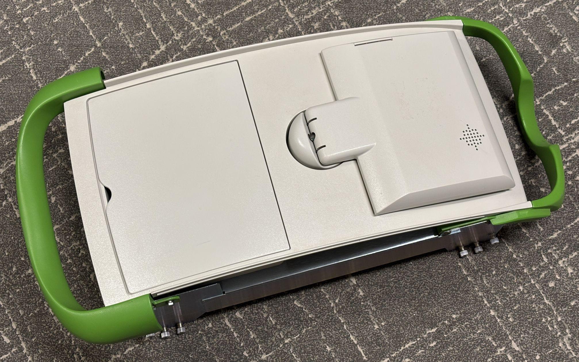
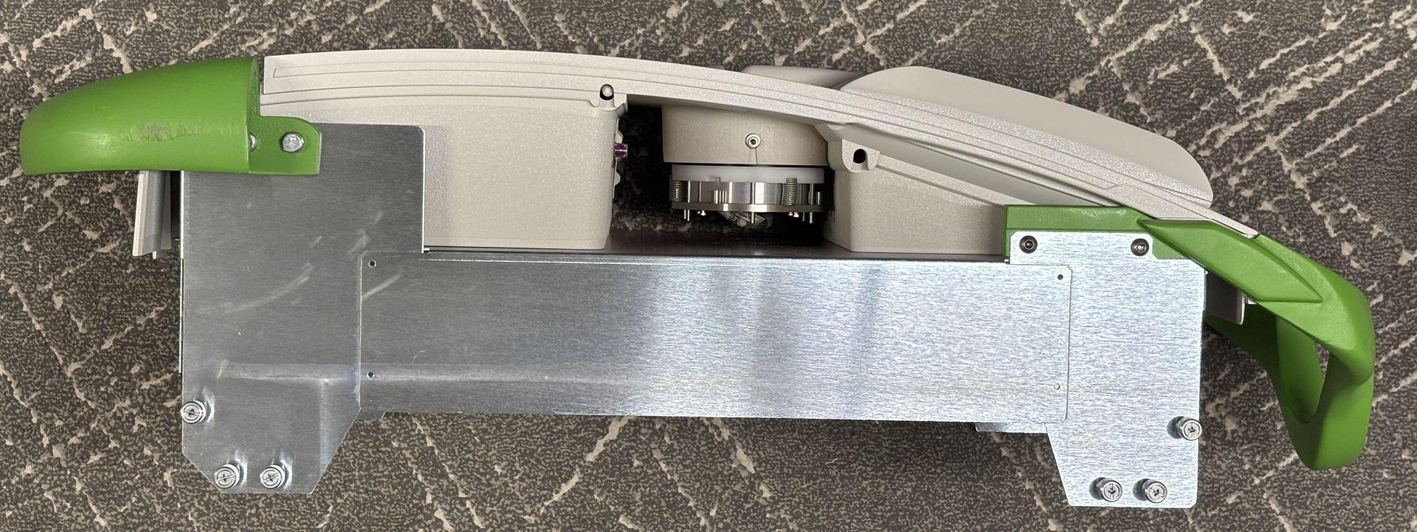
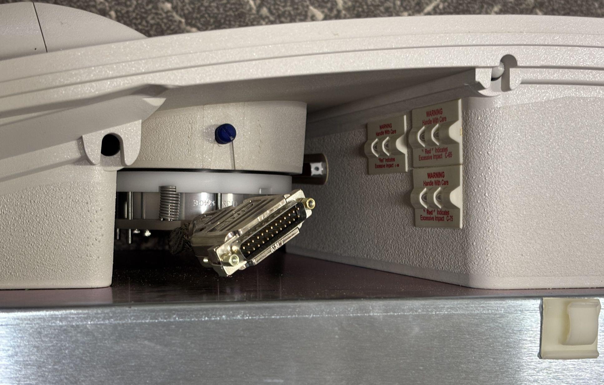
In the image below, the rotating mount for the touchscreen is visible, along with some shock and tilt sensors hidden inside the case.
Laser Head (Resonator)
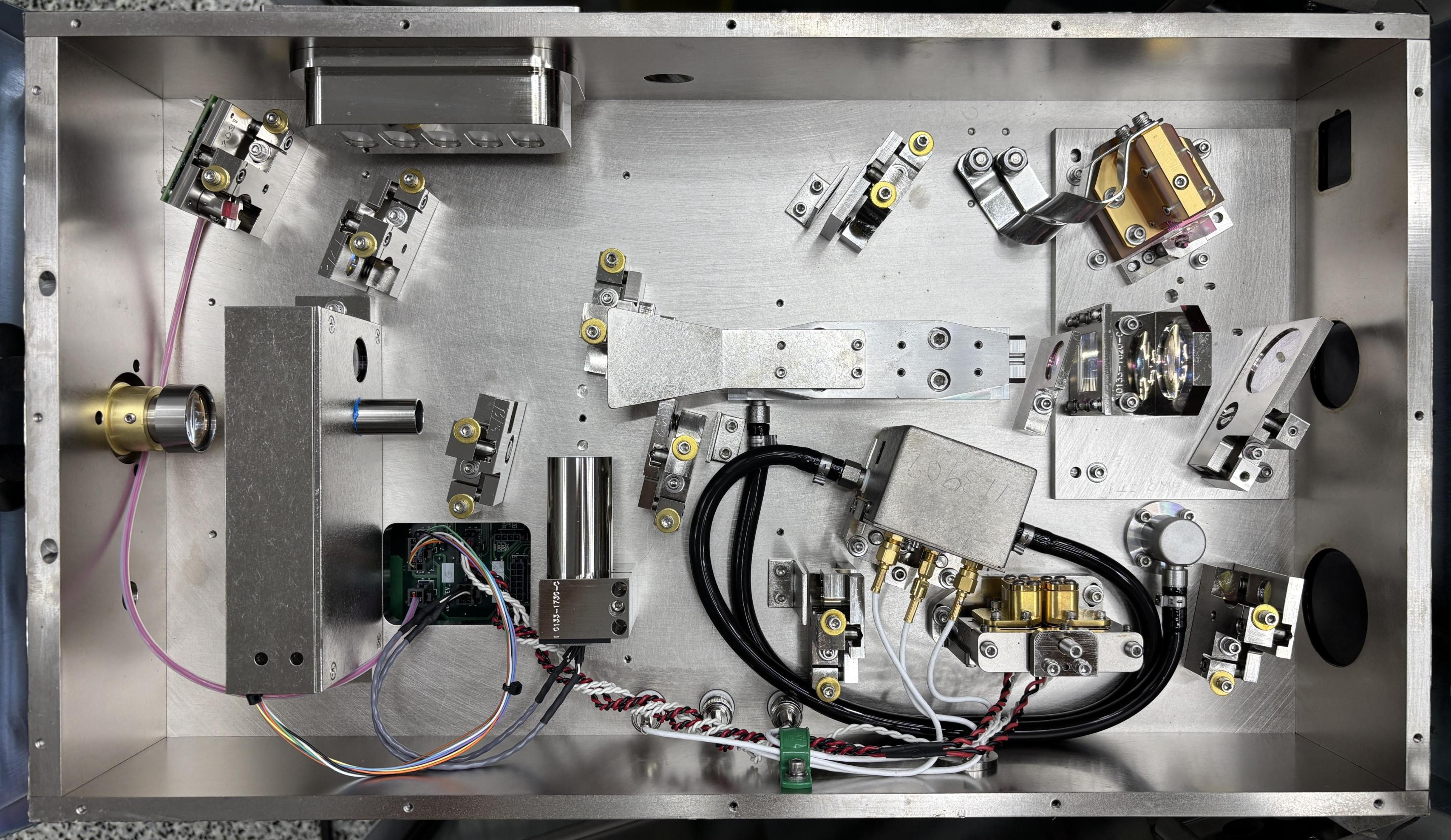
With the top cover removed, the laser head (resonator) is visible. This is the largest DPSS laser head we have ever seen. It's a rectangular, milled aluminum enclosure, that is secured to the frame by four bolts and vibration mounts. All connections to the resonator are on the bottom, and the output aperture and fiber connection protrudes through a hole in the front of the frame.
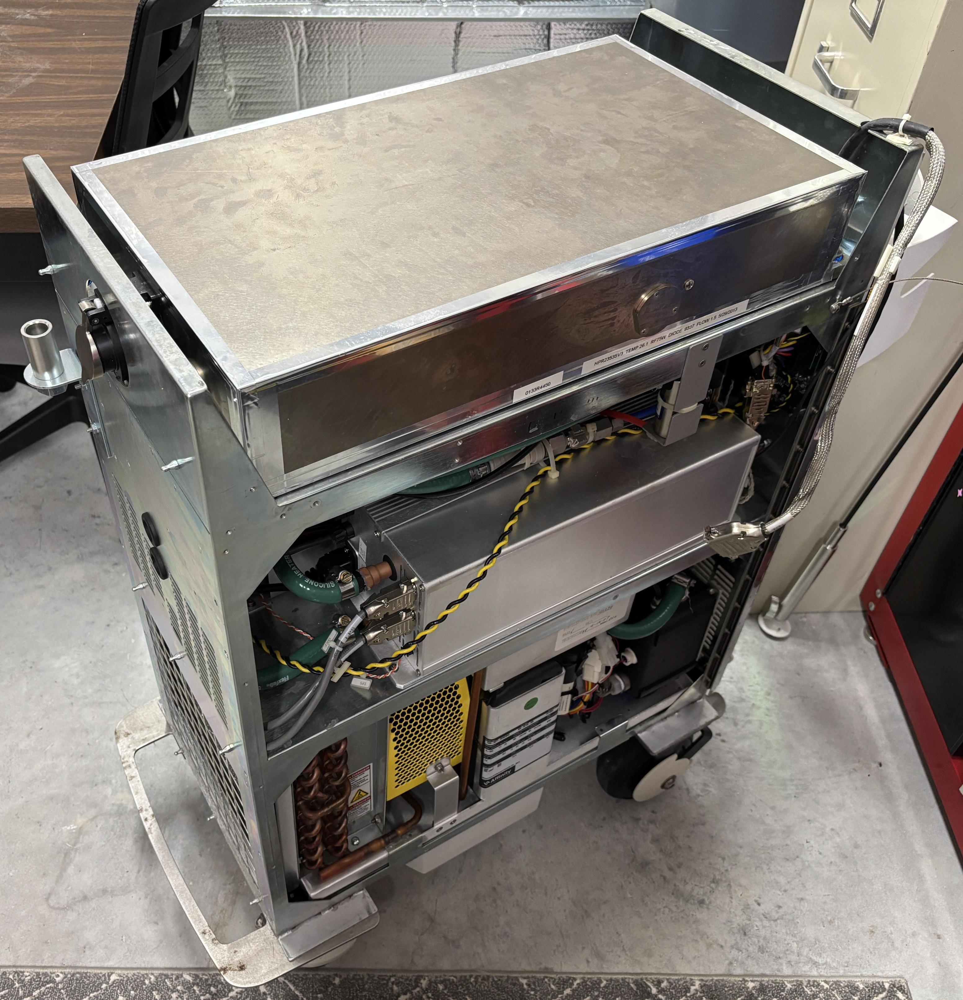
With the resonator removed, the bottom connections are visible. There are two sets of cooling water connections. The narrow blue and red tubes are for the laser diode, for which the flow is regulated by a valve below the resonator. The q-switch and YAG rod are cooled by the larger diameter hose barbs on the bottom of the resonator enclosure. High quality silicone hose is used for the water cooling connections throughout the system. Towards the top left of the image below are two studs and bolts, which are the pump diode power connections. The anode and cathode are electrically connected to the respective output studs of the laser diode driver. In a separate tray that extends below the resonator enclosure is a circuit board that is referred to as the laser control board (LCB). This board manages the crystal temperatures, monitors the photodiodes, controls the aiming beam, and controls the safety shutter. Two twist-lock connectors are installed in the tray, near the center of the unit. These are sealed passthrough connectors. The 17-pin connector carries the same CANBUS and RS-485 communication buses that are shared by the other modules. The smaller 6-pin connector is used to deliver power to the laser control board. Both the power and data connections go directly to sockets on the rear panel board. The thin black cable secured by foil tape is for the electrical contacts and thermistor within the fiber connection port. This cable goes to a connector on the rear panel board. Lastly, the three BNC connections on the middle of the bottom of the enclosure are for the q-switch crystal. The middle BNC is for a thermostat mounted to the q-switch baseplate. The left and right BNC connectors deliver RF power to each crystal individually.
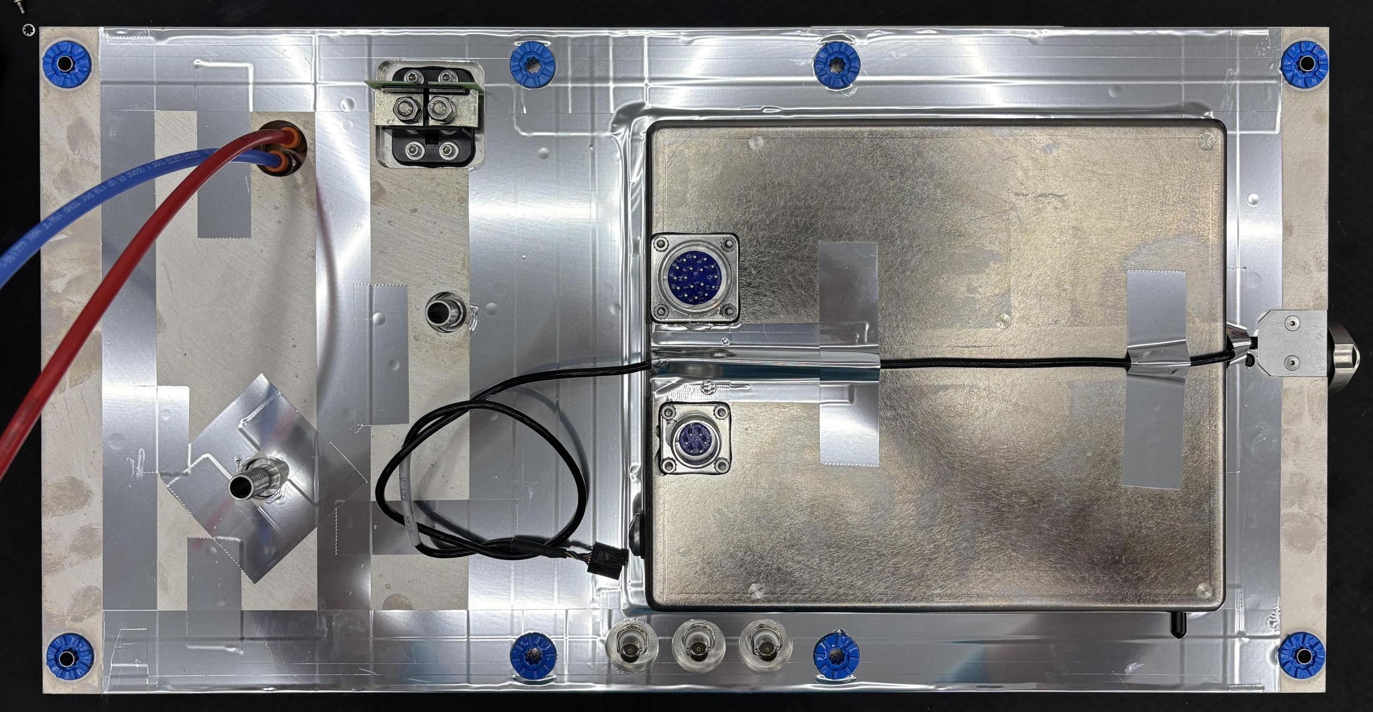
Below is a picture of the laser control board (0133-0440). This board monitors crystal temperatures, drives both TEC channels, monitors and controls the safety shutter, drives the aim beam, and monitors the photodiodes. It communicates with the rest of the system over the CANBUS network.
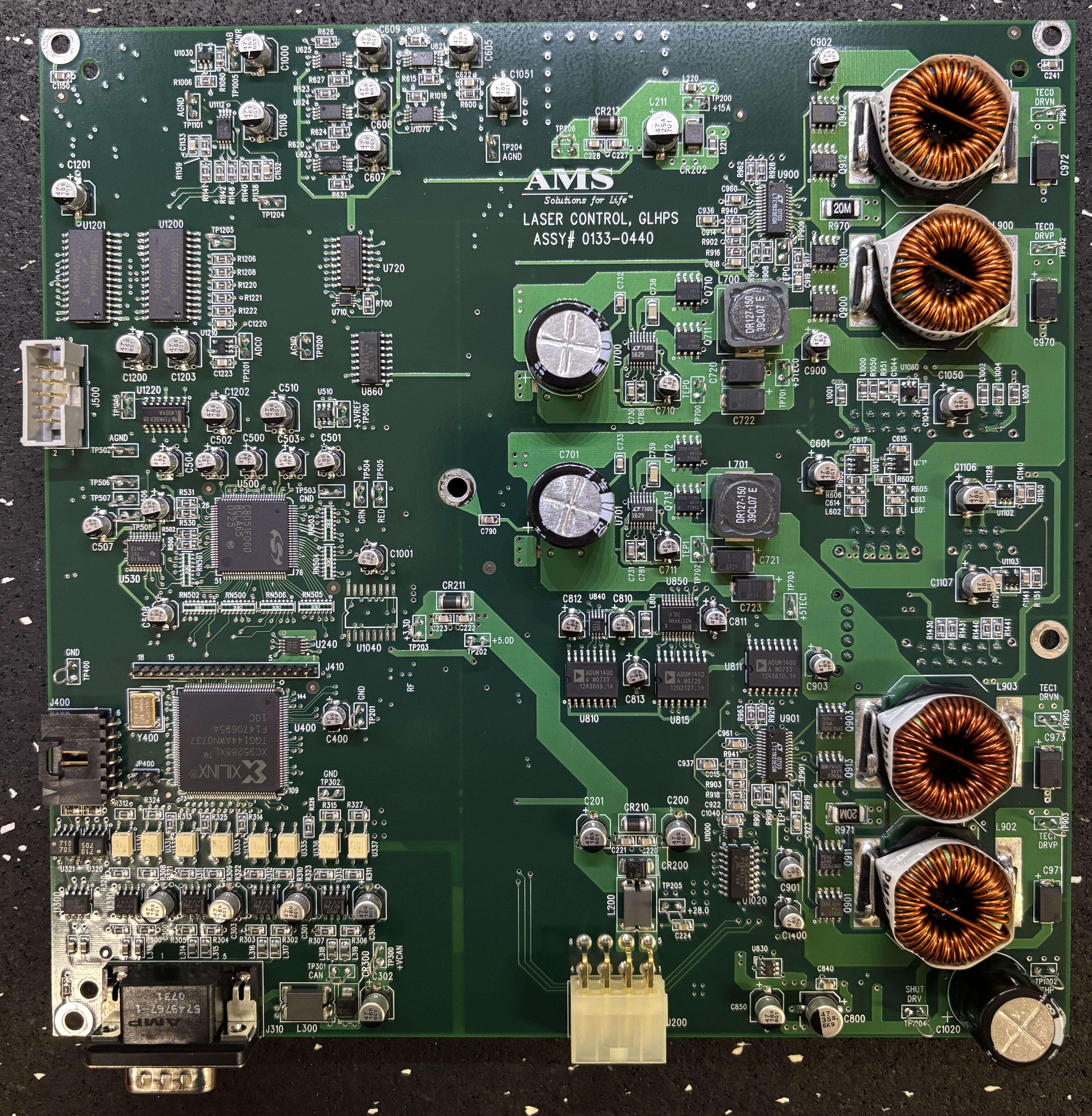
The top cover of the resonator is secured with several hex screws. Importantly, there is no sealing gasket, only foil tape applied around the perimeter of the resonator enclosure and any openings. In order to open the resonator, the foil tape must be cut or removed. The resonator should not be left exposed to the ambient air and moisture for very long due to the hygroscopic properties of the LBO crystal coatings. They will absorb moisture over time and can be completely destroyed if the resonator is left unsealed for a while or without suitable desiccant. It is very disappointing that AMS did not use a gasket, but this is specifically mentioned in the XPS service manual, which is a very similar system to the HPS. The manual also stresses the importance of changing the desiccant every 6 months to prevent moisture buildup. This resonator enclosure is made of several individual pieces of milled aluminum. It was likely too expensive for them to design them in such as way to accept sealing gaskets. Certainly doable, but not in their best interest. The desiccant access panel does use a gasket, allowing for easy replacement of the desiccant pouch. With the cover removed, the optics are visible. It's a Z-FOLD arrangement that includes an 808nm pump diode stack, two LBO crystals for second-harmonic generation (SHG), a q-switch for modulation, an Nd:YAG rod, and a safety shutter. Other ancillary components include dual photodiodes and an aiming beam. To learn more about the beam path and optics, please visit the link below for a detailed breakdown of the resonator, including a beam path diagram.
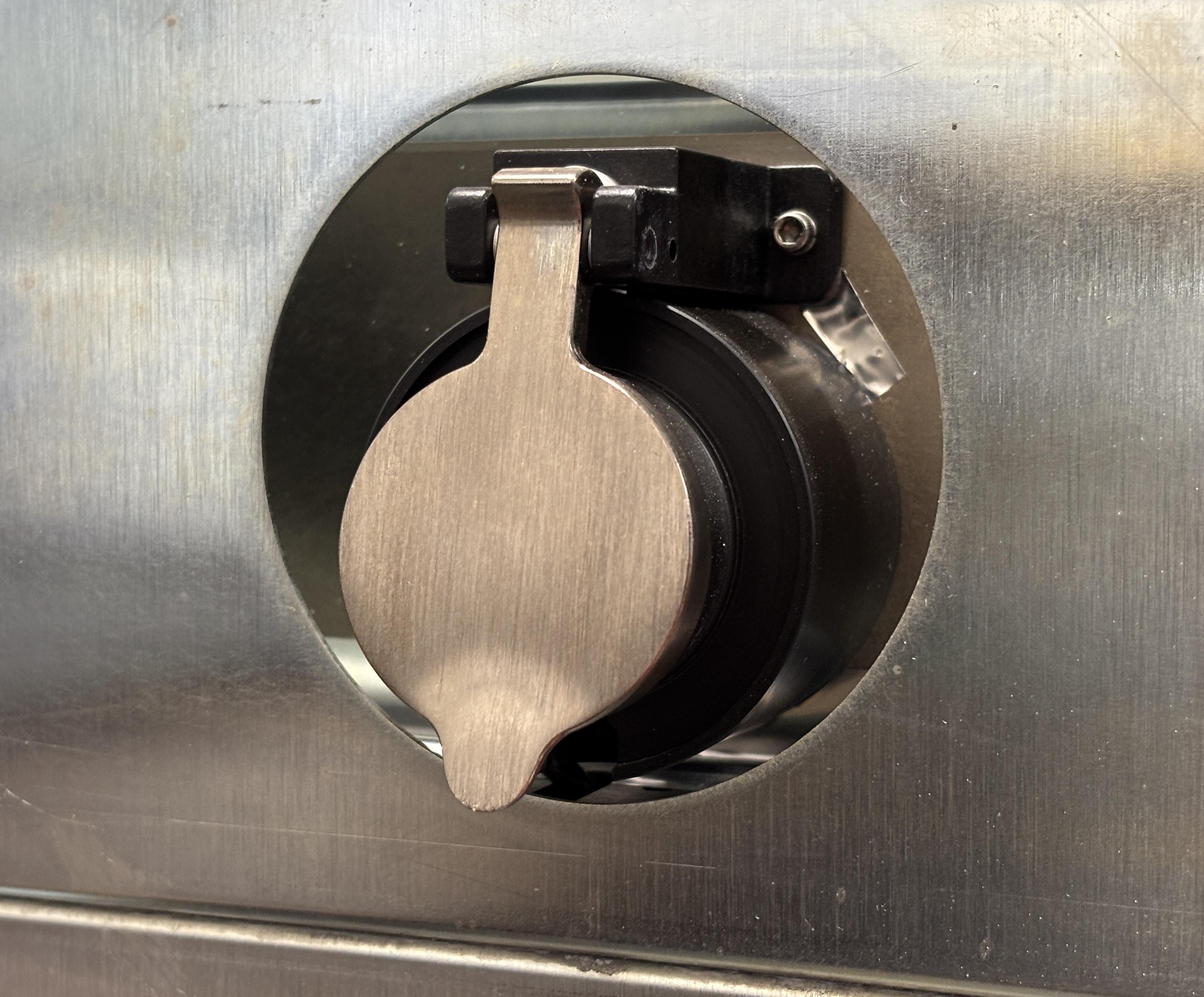
The fiber port is protected by a metal cover that automatically flips down over the port when no fiber is installed. The cover has a dampened auto-close mechanism that gives the operator a few seconds to insert the fiber before the cover springs downwards.
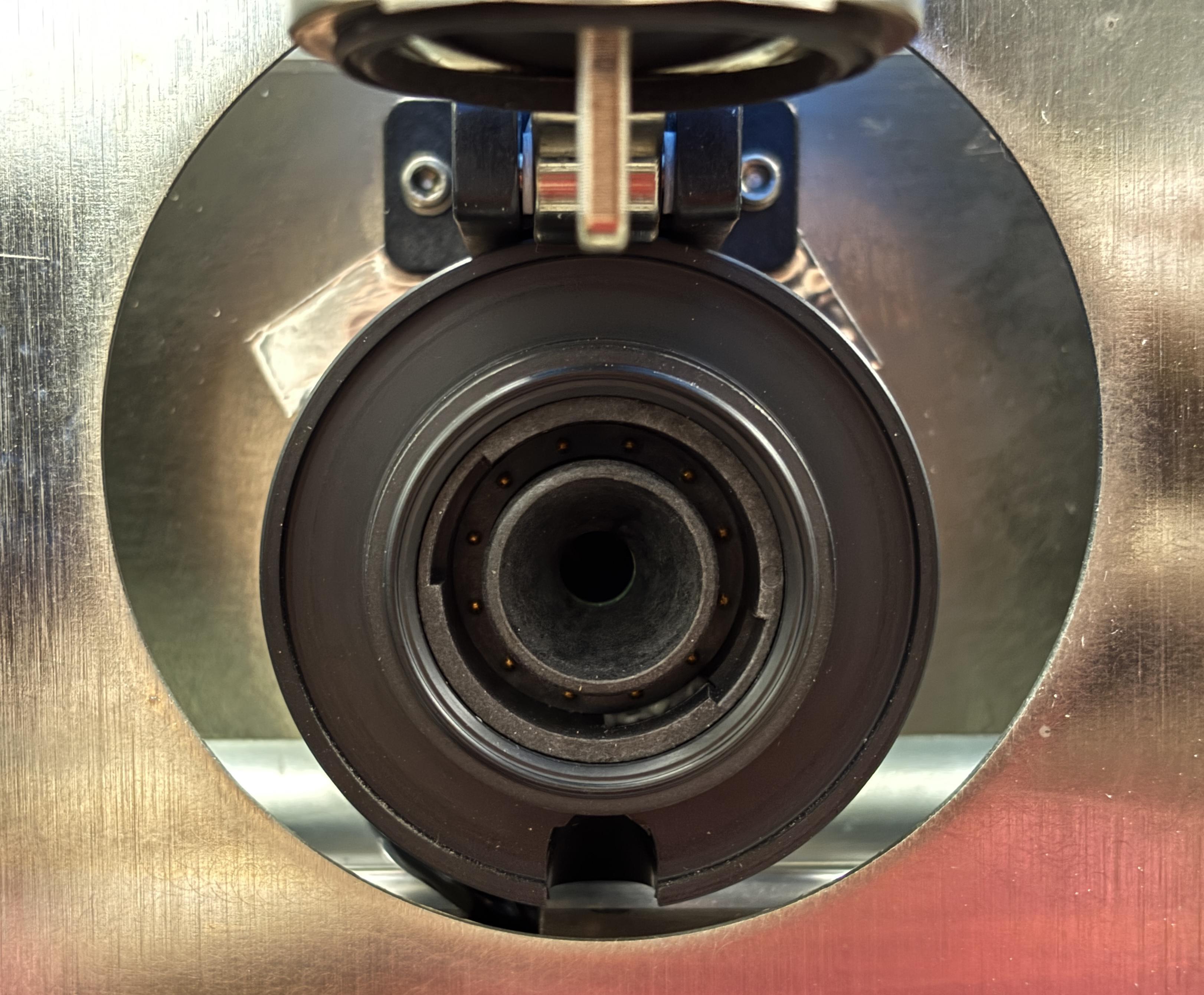
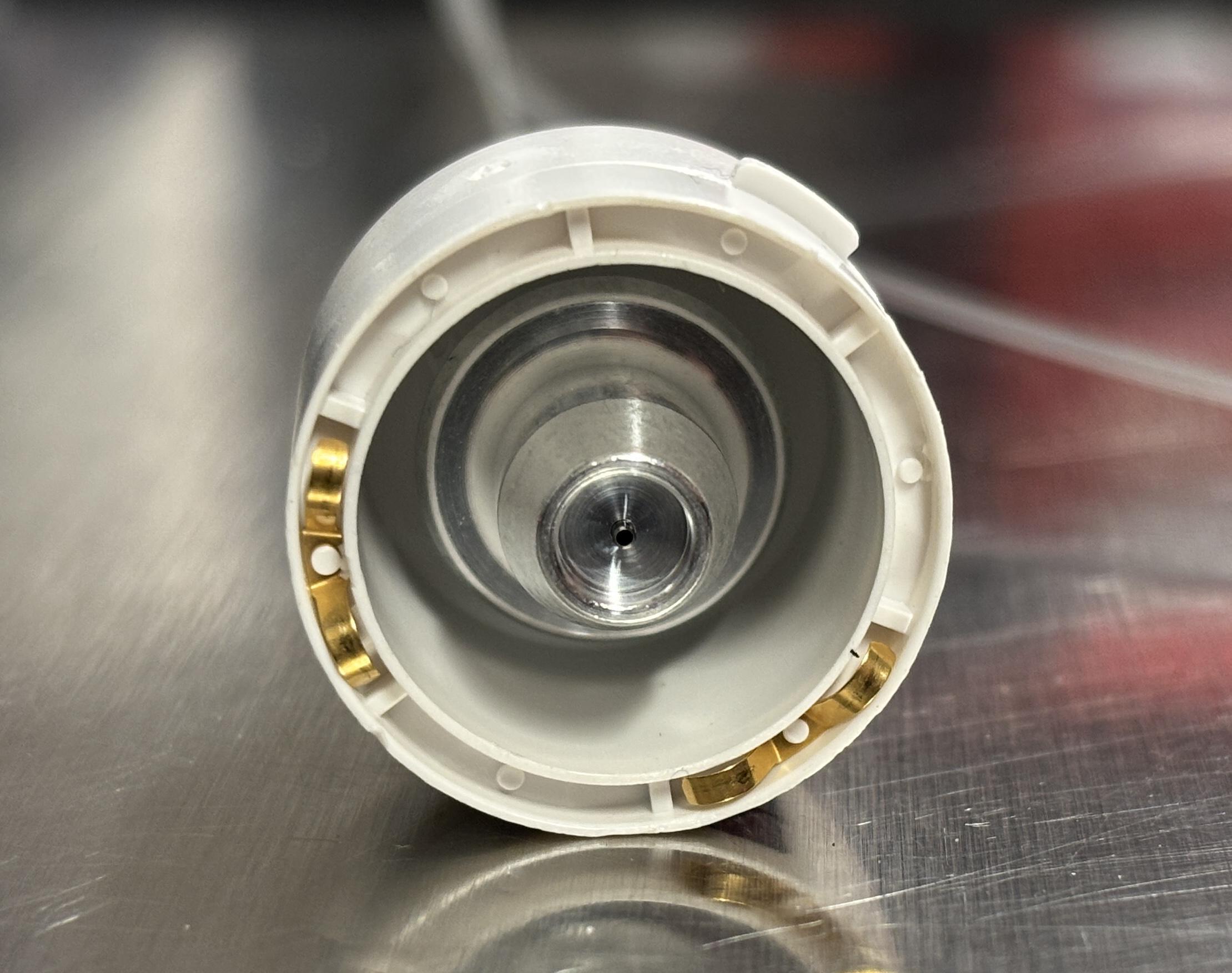
With the cover open, the fiber port is visible. It seems to be made of a combination of high quality plastic and metal, and has a rubber gasket to keep debris out. The laser passes through the center hole to the fiber. The metal contacts are used to detect the presence of the fiber and identify the model. The keying accepts two plastic tabs on the fiber connector which rotates about 45 degrees to lock into place. A metal finger on the inside of the cover presses against the plastic body of the fiber to prevent the cover from pressing against the delicate optical fiber itself.
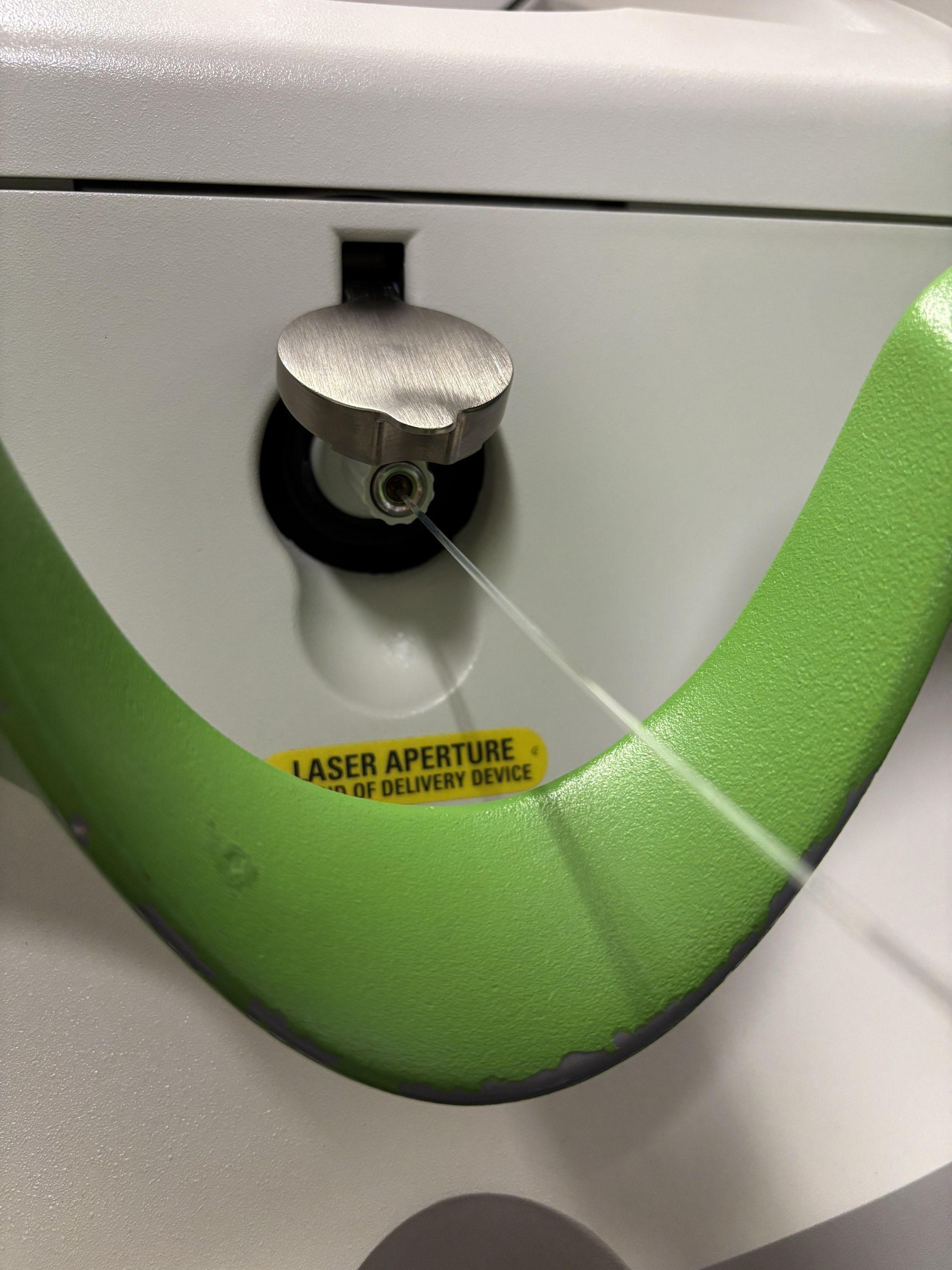
Below is an image of a fiber inserted into the socket.
Smart Cards, Optical Fiber, and DRM
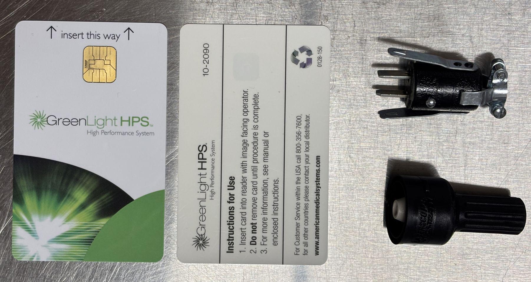
In addition to the initial purchase of this unit, AMS also made their money on consumables. The Greenlight HPS uses disposable optical fibers to deliver the laser beam to the target site in a safe and controlled manner. These fibers mate with the output aperture port and make electrical contact with the identification pins as mentioned earlier. The fibers also come with a smart card, and we estimate each kit cost around $1,000. The smart card is a sinisterly brilliant form of DRM (digital rights management). Since the fibers were intended to be disposable, single-use devices, AMS needed a way to enforce that. The smart card inserts into a slot located on the side of the touchscreen housing. Using a cryptographically secure connection, the Greenlight HPS processor would verify the authenticity of the smart card and ensure the specifications matched those of the attached fiber. If everything matched up, and the software validation was successful, the system would be ready for use and capable of laser emission. If any part of this process fails, the system refuses to enable laser output. Not only did this prevent counterfeit fibers from being used, but it also enabled AMS to set a lifespan for each fiber card. Energy in joules is the selected unit of measure for this process. For example, after 275,000 joules of energy has been emitted through a fiber, the system would permanently disable the associated fiber card. The capacity in joules was printed on the fiber packaging and automatically read by the system through data stored on the card and the arrangement of electrical contacts on the fiber. Additionally, the system was capable of warning the user when they had less than 50,000 joules of energy remaining on the fiber. Lasing time depends on how the system was used, such as the intensity of coagulation and vaporization, along with the model and capacity of the fiber. Pictured below are two smart cards, a spare remote interlock plug, and a fiber port dust plug.
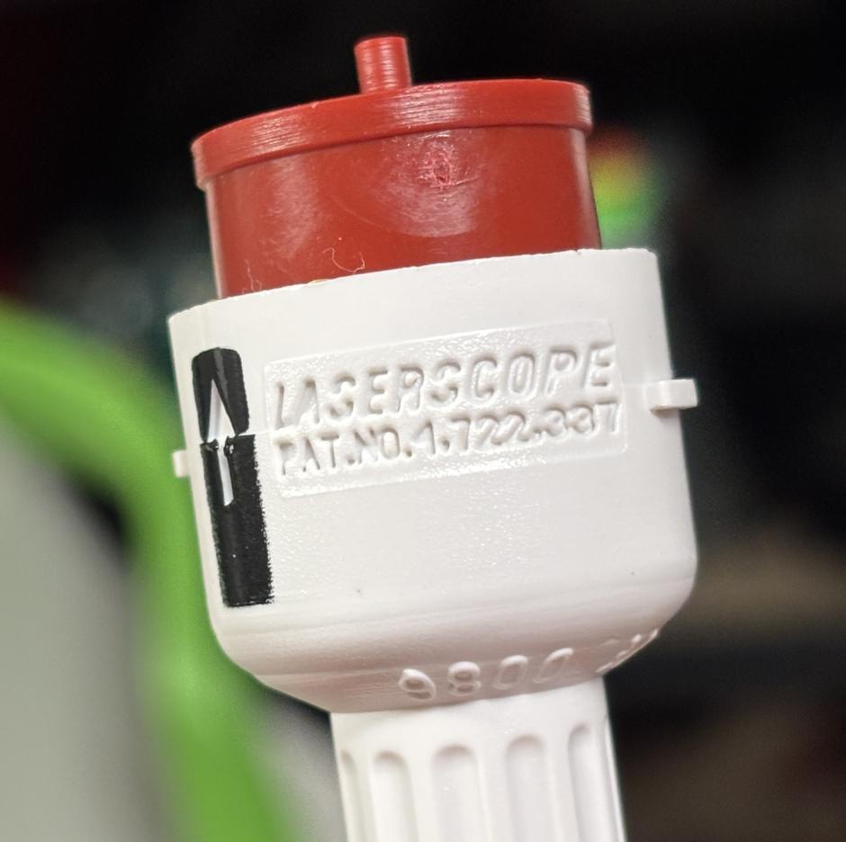
Below is the plug end of a fiber that would be inserted into the fiber port on the HPS resonator. It's made of plastic and uses the two tabs to twist and lock into the fiber port. The metal contacts simply short out a specific set of pins to identify the fiber to the laser system. Based on the arrangement of injection-molded cavities, these metal contacts could easily be re-arranged to identify the various types of disposable fibers.
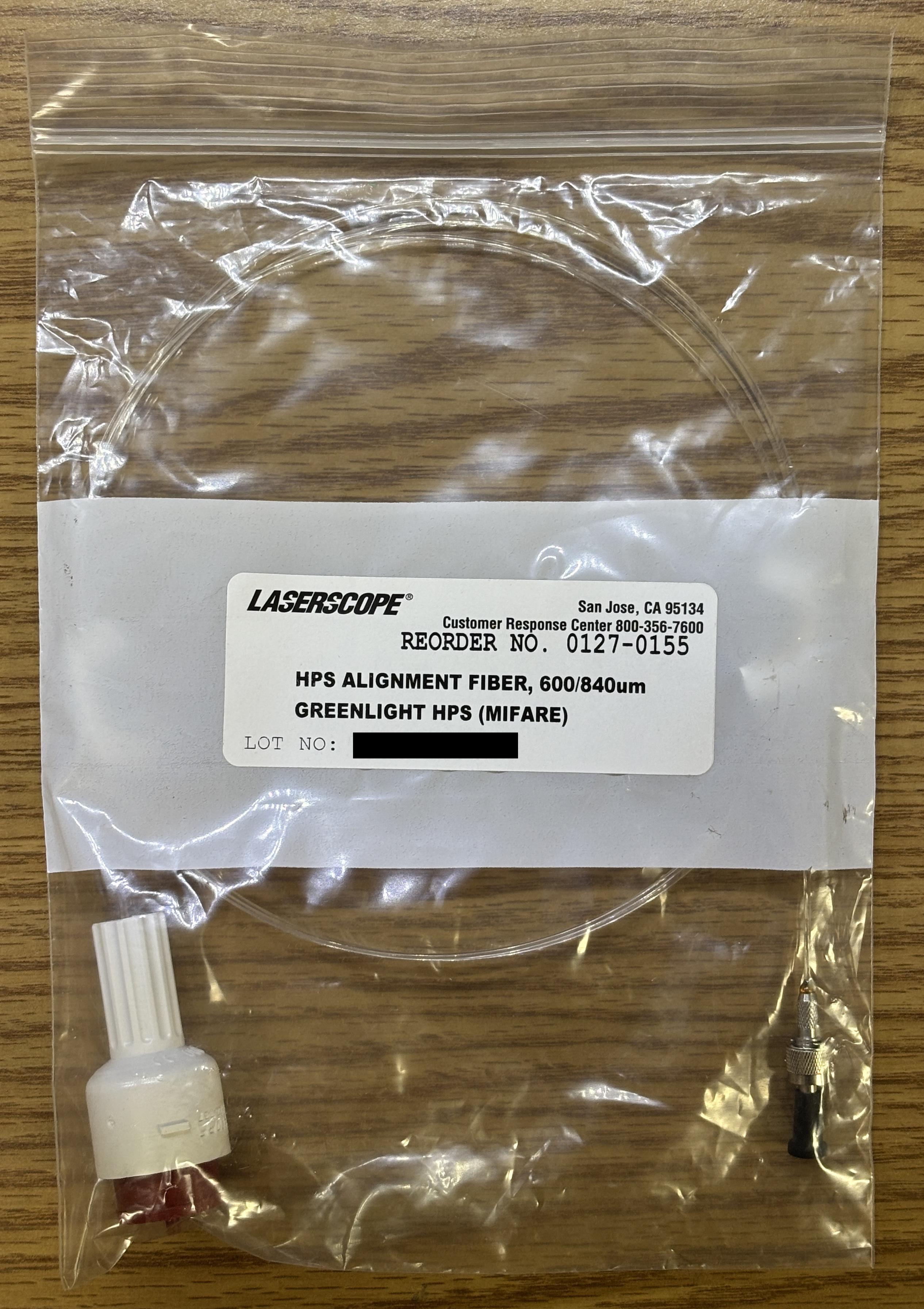
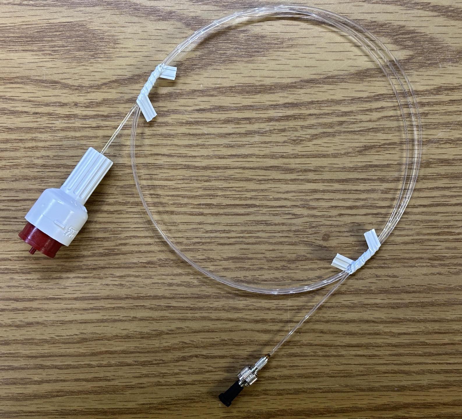
Even though our Greenlight HPS did not come with any fibers, we found an HPS alignment fiber for sale online. This is a part we had never seen before, up until this point. It has a reorder number of 0127-0155, which follows the Laserscope/AMS convention. The fiber uses the same input connector as the surgical fibers would use, but has a metal SMA connector on the output side. It's about 3 feet long and is just a bare plastic fiber with an outer diameter of ~1.25mm. It has no outer shielding or jacket and was likely used for alignment and calibration, as the name suggests. This is the best possible accessory to find as it converts the nonstandard, proprietary fiber output to something common and usable. From there, collimators and other beam-forming optics can be connected. Not to mention, this makes it easier to get the beam where you want it, instead of just having it exit from the front of the unit. The packaging of this accessory mentions MIFARE, which refers to the ISO/IEC 14443 standard for 13.56 MHz contactless (RFID) smart cards. This implies there is some sort of digital storage device embedded within the fiber housing, similar to an NFC card. However, this particular system and other AMS Greenlight HPS units we worked with never implemented any RFID based communication. The fiber port assembly does not contain any sort of antenna that would facilitate RFID communication. Additionally, we were unable to read any data from the plastic end of the fiber with an NFC card reader or 13.56 MHz access control reader. Furthermore, we located an FCC ID certification record (UEA-10-007X) that contains images of an RFID antenna and related logic/connections implemented in the resonator and on the laser control board. It is our understanding that earlier Laserscope branded Greenlight HPS units implemented RFID authentication/communication with the disposable optical fibers, to be used in conjunction with the smart cards. This evident by the mandatory FCC part 15 warning label present on the rear casing of the Laserscope units. Later AMS branded units seem to have omitted this feature, which is also evident by the absence of the FCC warning label. Perhaps it was removed after Laserscope was acquired by AMS to reduce costs, or removed to reduce issues with the authentication process. The AMS Greenlight XPS may implement RFID communication with the fiber, but we cannot confirm or deny this.
The fiber and smart card DRM system implemented in the AMS Greenlight HPS is flawed in two significant ways. First, the system only writes usage to the smart card at specific intervals/after a specific amount of usage. We haven't figured out the exact value, but if you shut off the system or remove the smart card before this interval, restart the system, and re-insert the card, the usage will reset back to zero joules and zero seconds of lasing time. Running the system for no longer than ~10 minutes or ~1000 joules (estimates, not exact) and restarting before the next session would essentially permit the indefinite use of a fiber card. The other major flaw is related to the relationship between the fiber and the smart card. The earlier Laserscope Greenlight HPS units and disposable fibers contained a unique identifying device, such as an embedded smart card chip or EEPROM, which was then compared against values in the cryptographically-secure smart card. As mentioned earlier, this does not seem to be the case with the AMS branded Greenlight HPS units. The fiber connector only includes a few strategically-arranged metal contacts which short specific pins within the laser output aperture and fiber connection plug. This only allows the system to determine a model of fiber, not any sort of unique ID such as a serial number. With this arrangement, there aren't enough combinations to create a unique identifier. Therefore, a single fiber could be re-used as long as its model or capability ID matched what was on the subsequent smart card. This completely undermines the safety aspect of this DRM system, further reinforcing the fact that it's really about the money. If AMS really wanted to prevent fibers from being overused, they too would contain a unique identifier or some device that could be disabled or blacklisted by the system, like the smart card. It is bizarre that Laserscope implemented the RFID fiber identification feature, but it was seemingly dropped in the newer AMS models. This likely never became an issue, as operators are trained to simply dispose of the fiber and smart card after the procedure, and utilize the smart card that comes with each new fiber. In theory, if an operator were to continue using the same fiber with smart cards belonging to new fibers of the same variant, the integrity of the original fiber could break down and present a safety issue. Furthermore, researching patent number 4.722.337 (US4722337A) reveals an earlier design of this fiber interface system. This patent describes the usage of precision resistors (of various values) contained within the connector of the disposable fiber. These resistors would be connected to the same set of electrical contacts that mate with contacts within the fiber port. Using technology similar to early GM key ignition systems, the Greenlight HPS processor would be able to read these resistances. It is unclear as to whether this would be used to uniquely identify the fiber and associate it with a smart card, or if it was just a more advanced way of determining its specifications and capabilities. Regardless, the patent alludes to the fact that this method was dropped in favor of just shorting pins with electrical contacts, which minimizes cost and complexity.
Foot Switch
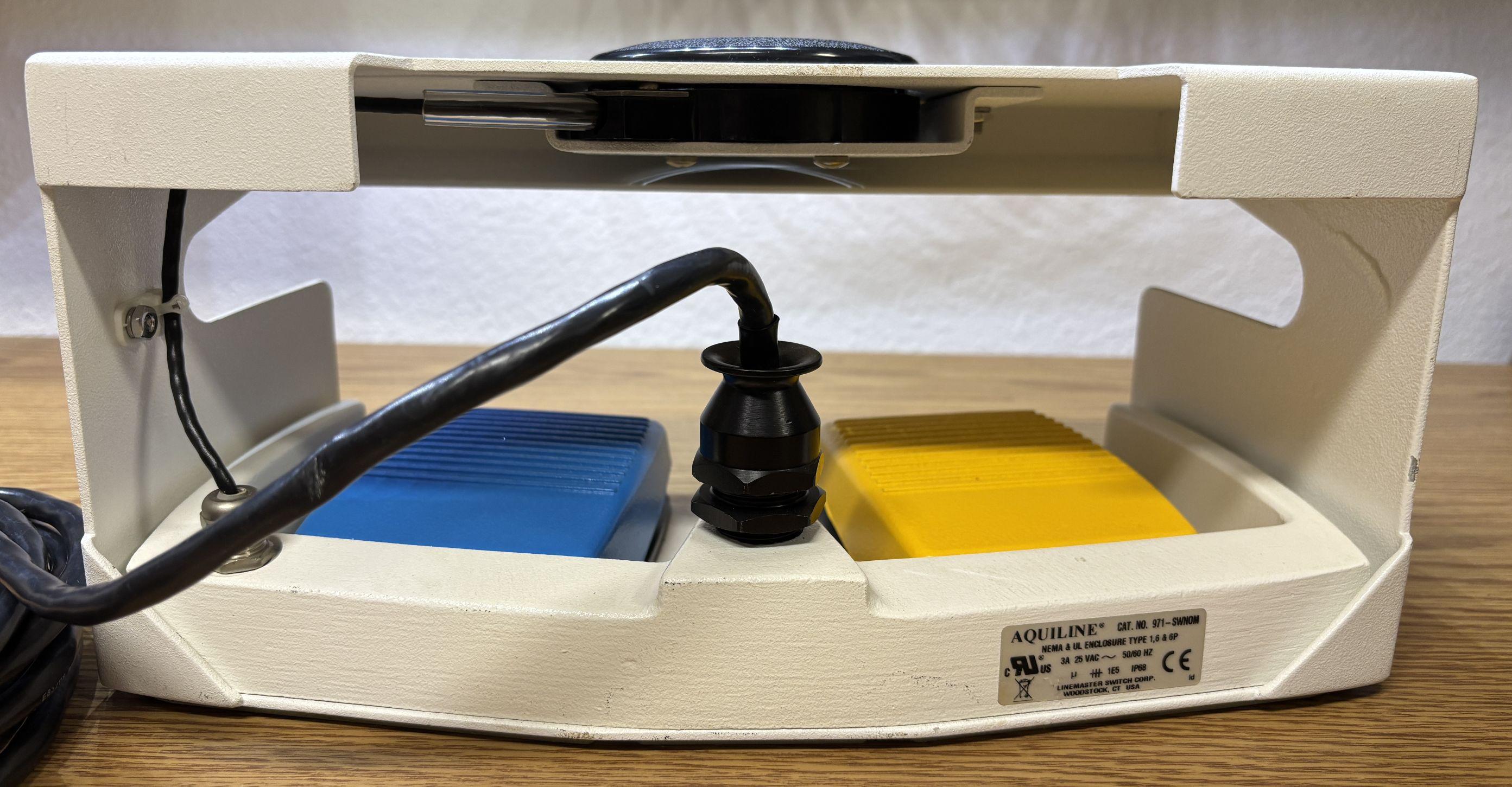
The foot switch assembly features 3 main components: a ready/standby button (black), a vaporize pedal (yellow), and a coagulation pedal (blue). The foot switch connects to a 9-pin, twist-lock socket on the back of the unit and allows the operator to control laser emission while keeping their hands free. The foot switch wire harness includes a chassis ground, C/NO/NC contacts for the vaporize and coagulate pedals, and a C/NO set of contacts for the ready/standby button. This also allows the system to detect whether a foot switch is connected.
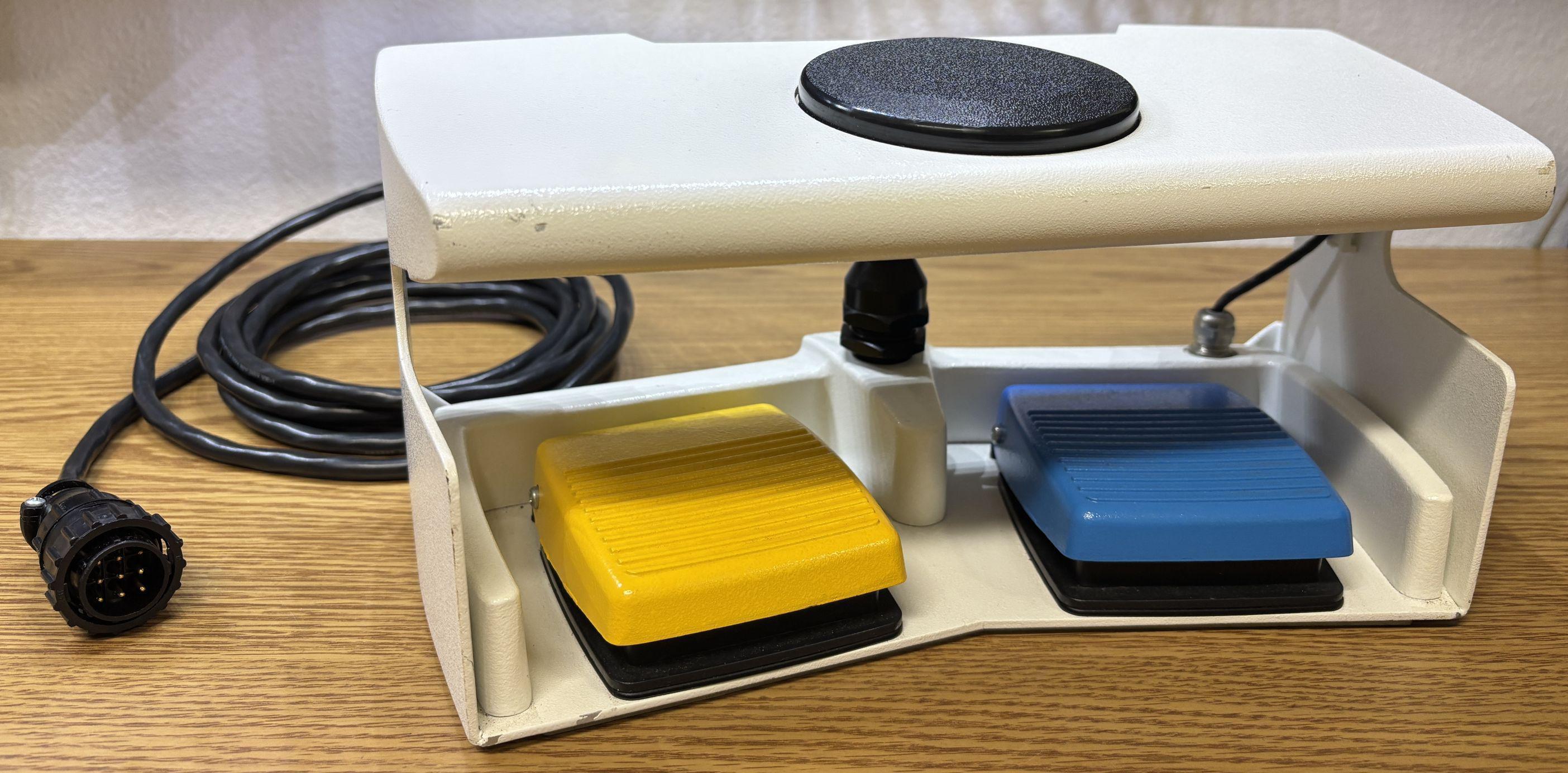
The white metal frame is quite sturdy, and features some anti-skid feet on the bottom. The wiring is adequately protected from damage or strain. The assembly (frame and switches) appear to be part of the AQUILINE series manufactured by LineMaster Switch Corp.
Powering Up the Greenlight HPS
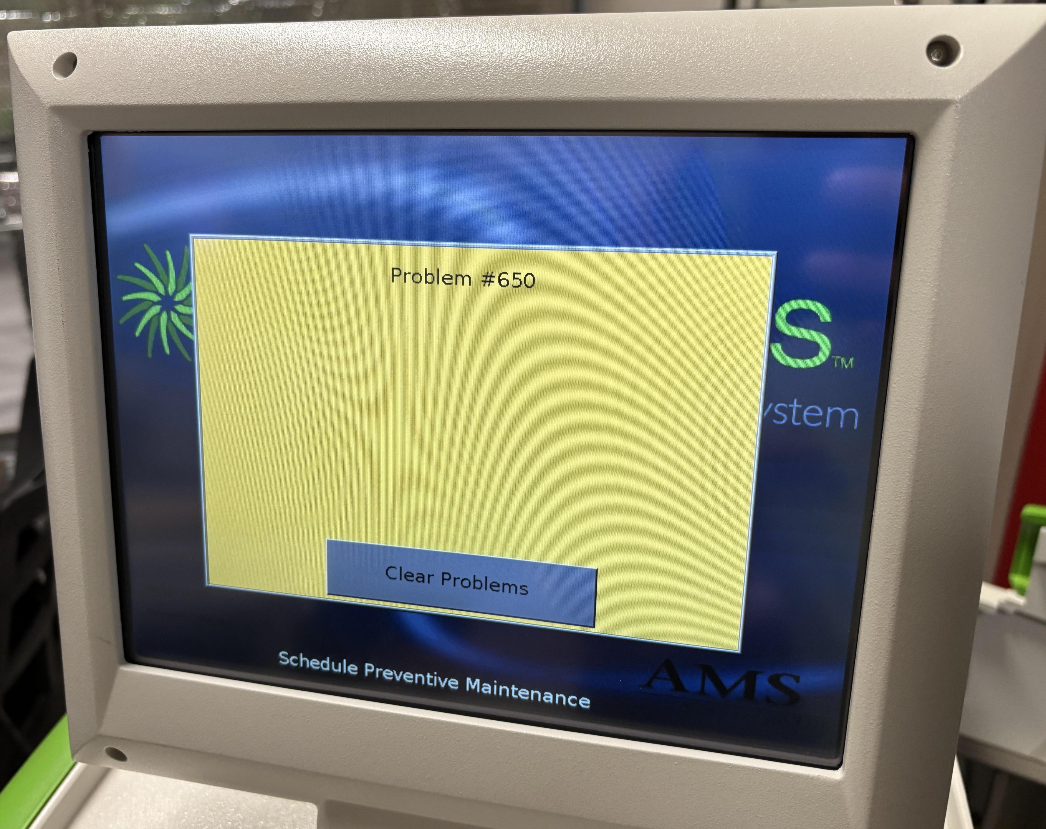
Starting up the Greenlight HPS is straightforward. Plug in the AC power cable and switch the breaker on. It won't actually start at this point, but the autoselect board will come alive and a small fan mounted in the bottom tray will begin running. Once the key switch is turned on, that signals the autoselect board to supply power to the rest of the system. At that point, everything comes alive. More fans start, several relays click, and the chiller will eventually start. In our case, the chiller started and then stopped a few seconds later, and PROBLEM #650 was displayed on the screen. AMS provides only a basic table of problem codes based on the faulting module (chiller, diode driver, resonator, etc.) All you get to know is where the problem is, not what has actually gone wrong. After some troubleshooting, we determined that the reservoir level sensors were not being triggered. This was because essentially all the water had been drained from the loop. This is the proper procedure when storing or transporting the unit. Shortly after being energized, the chiller shut off to protect itself and the pump, as running dry will cause damage.
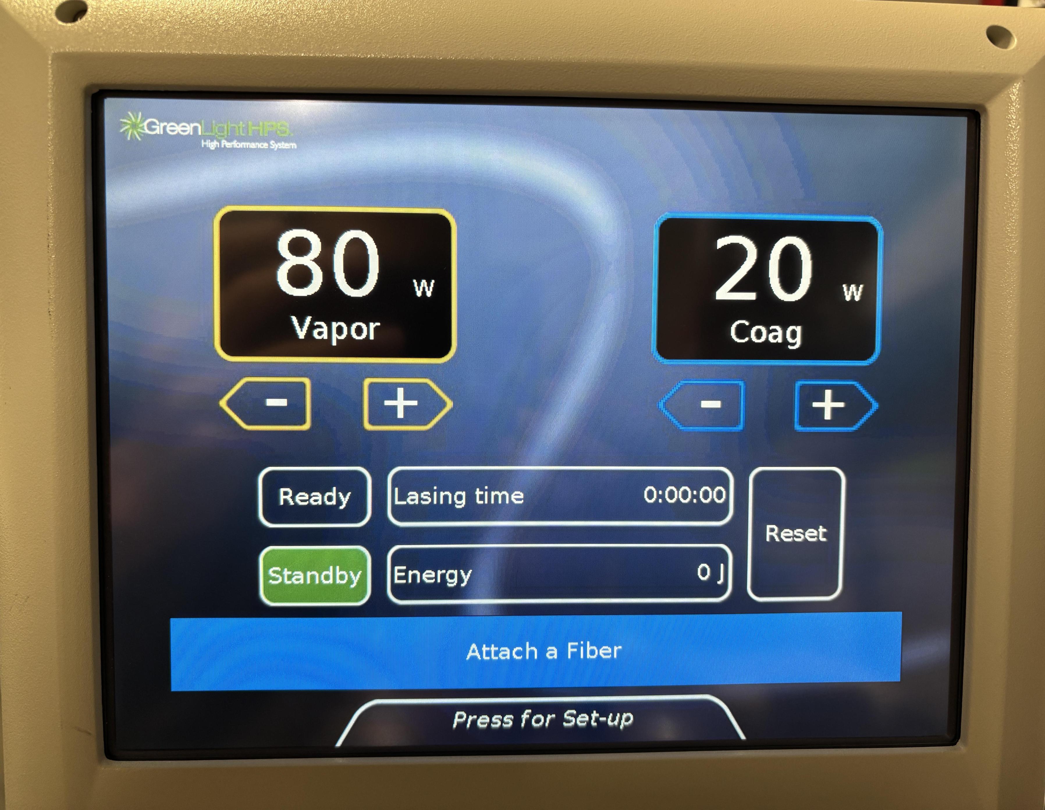
Filling the reservoir up with about half a gallon of de-ionized (or distilled) water fixed this problem immediately on the next startup. The chiller will start pretty quickly after the key switch is turned on, but the system does have an anti-short-cycling delay built in. This will delay the chiller startup by several minutes if it ran recently or the system faulted during the last run. While booting, the system displays a countdown timer with an estimate of the remaining time until the system is ready for use. During this time, an assortment of self tests are taking place. The system checks to ensure all modules are online and responsive, checks the chiller to make sure it's running, tests the safety shutter, and ramps the diode up and down through several power setpoints. Once the system completes all self tests, the home screen is displayed (pictured below). The blue rectangular section displays status messages that require attention, such as "attach a footswitch", "attach a fiber", or "insert smart card". Once all conditions are satisfied, this box will go away.
Once the foot switch is connected, a usable smart card is inserted, and a suitable fiber is attached, the system can be taken out of standby and put into ready mode by touching the button on the screen or pressing the black circular button on the foot switch assembly.
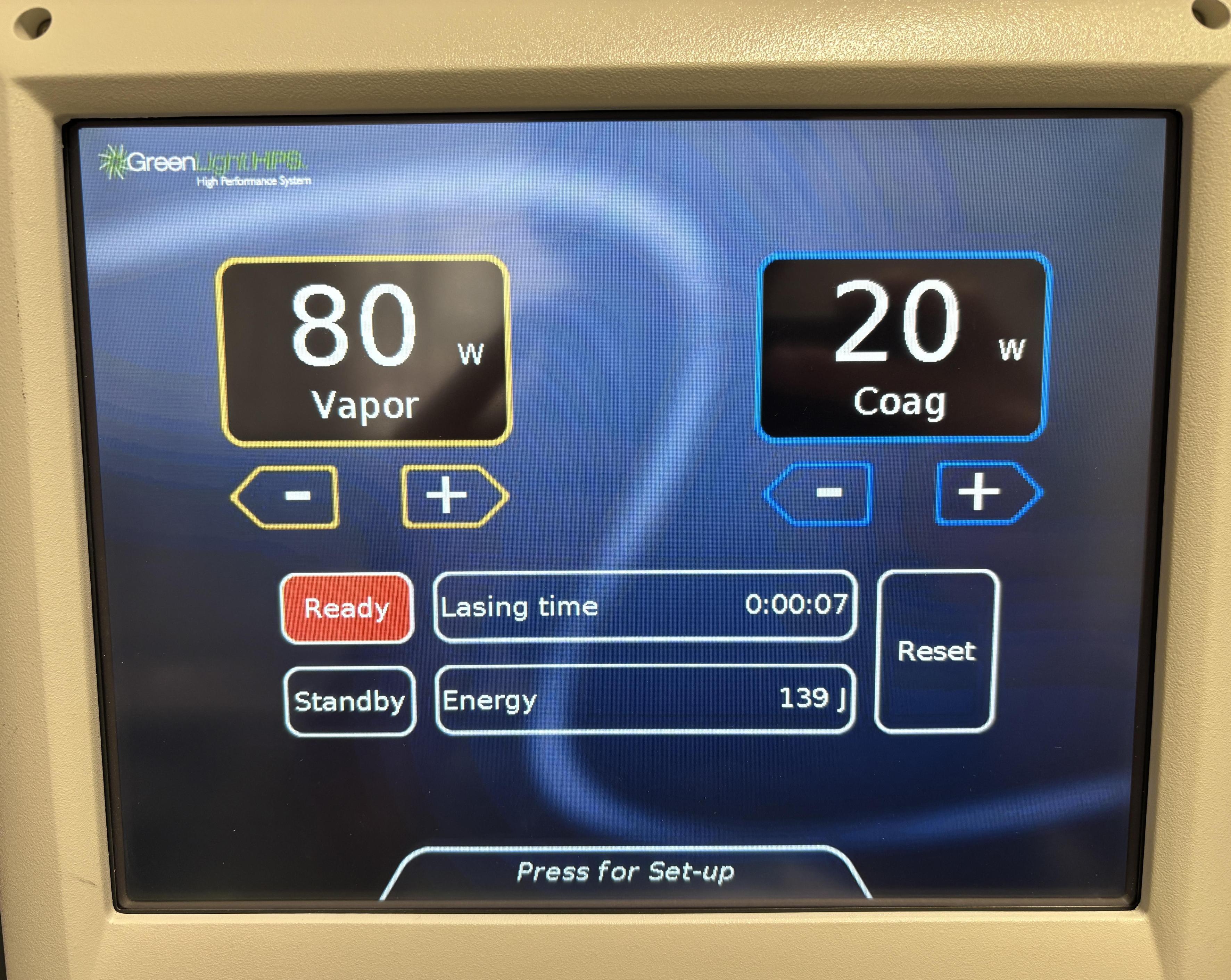
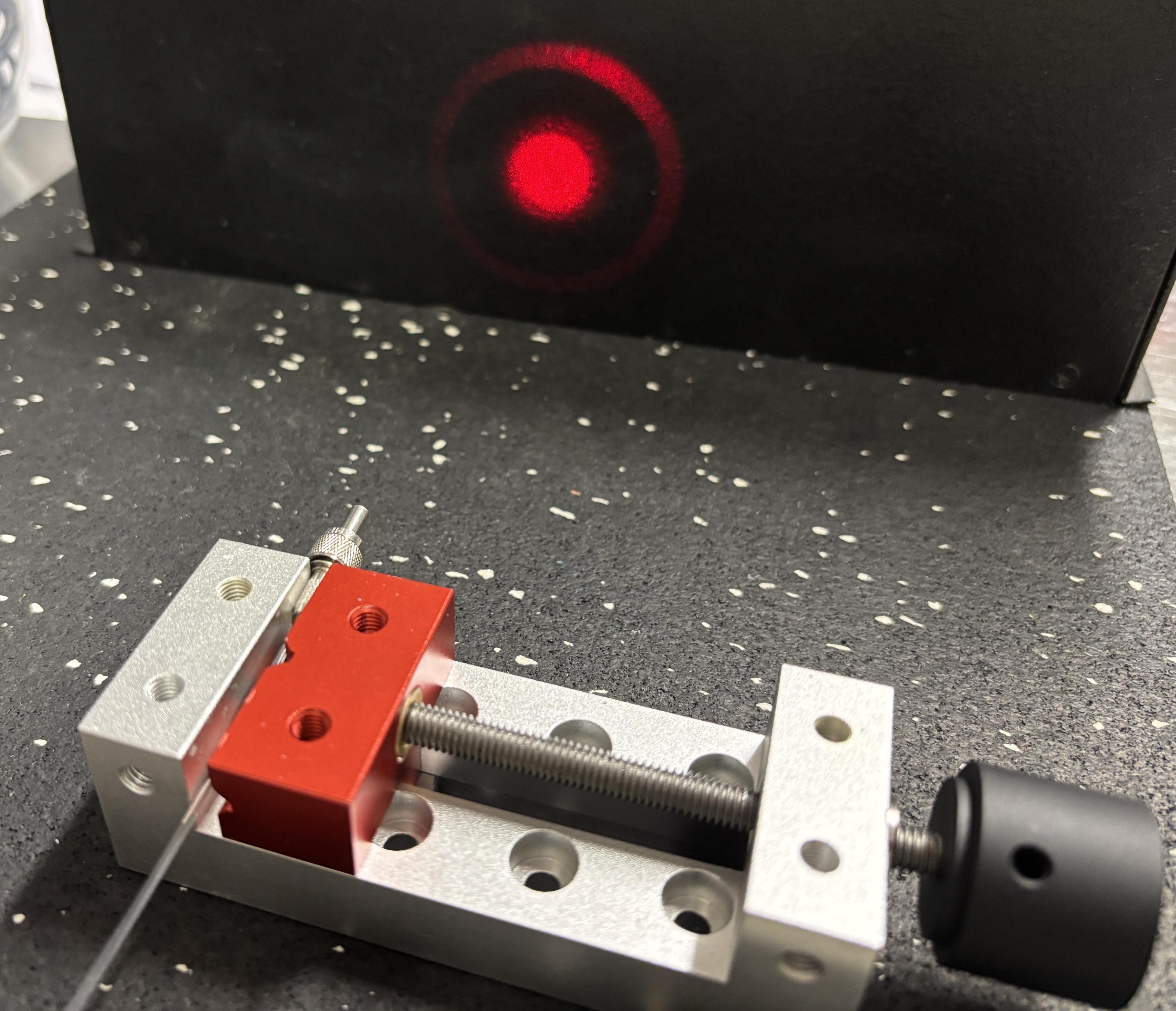
When the system goes into ready mode, the shutter opens up with a loud clack, and a voice announces "READY". At this point the laser is armed and dangerous! The red aiming beam is emitted through the fiber and is used to determine where you want the surgical beam. Be very careful where the beam is aimed, and ensure you're wearing your safety glasses at this point. The next step is the point of no returns.
Pressing the COAG (blue) pedal on the footswitch will activate the coagulation surgical beam. Pressing the VAPOR (yellow) pedal will activate the vaporization surgical beam. Both beams are dangerous, but the vaporization beam is downright diabolical. It's designed to vaporize tissue, so just imagine what it will do to your eye, skin, and sanity. Be extremely careful, and remember that you are dealing with a pulsed laser, so the 120 watt max optical output power does not tell the whole story. At last, the brilliant beam of 532nm green. The beam diverges quickly, but is still amazing. We are working on a viable solution for collimating the beam, and will update this page once we get that sorted out.
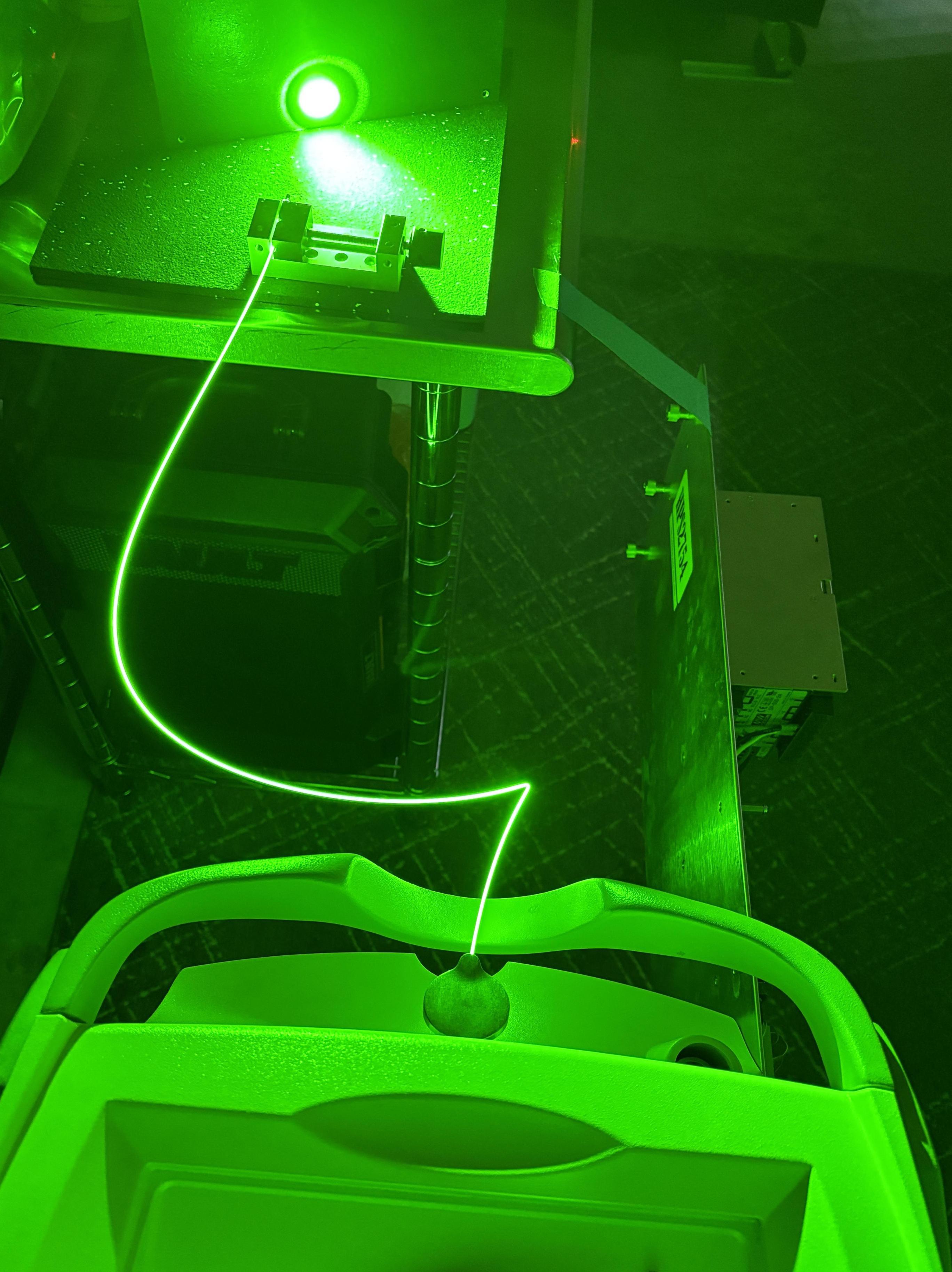
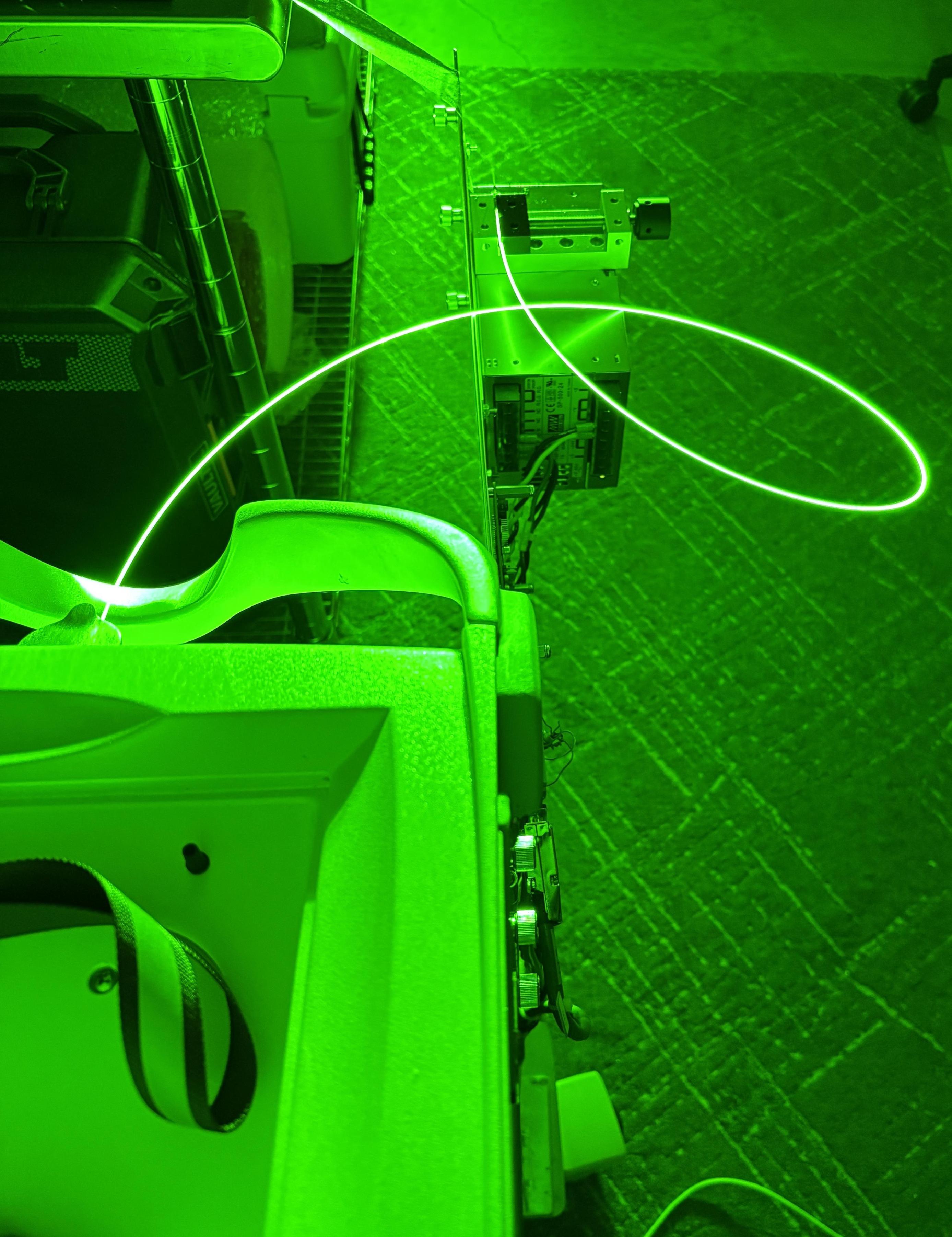
The illumination of the fiber is spectacular as well. It's odd that there is no shielding or outer jacket. Keep in mind that the system is logging and keeping track of every second a surgical beam is emitted. It has the equivalent of an odometer that collects lifetime energy in joules and also has a per session joule counter which is used as part of the FiberLife and DRM implementation.
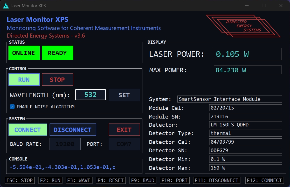
As expected, Greenlight HPS beam packs a real punch. Our power meter measured an 80 watt vaporization pulse at ~84 watts and a 20 watt coagulation pulse at ~21 watts. The HPS is probably the more accurate of the two as our sensor has not been calibrated in a while. Also, this does not take into account the pulsed operation of this laser, which could skew the reading.
Hacking the HPS
The purpose of this project was not to just buy and mess around with a Laserscope. Even a 120 watt laser gets boring after a while. Our next goal is to defeat the DRM. These units have been "undefeatable" for quite a while, or those who have successfully hacked them to run without the smart cards refuse to share that information. At Directed Energy Systems, we believe in sharing information with others. If they misuse it, that's on them. We are still working on this project, but have made significant progress. Right now we're at a crossroads with two choices. Reverse-engineer the CANBUS and RS-485 communication system and take control of the modules in their current state, or design and fabricate custom boards that can be installed in select modules, giving us full control using a simplified interface. Each option has pros and cons, but both have proven to be time consuming and challenging. If you're interested in learning more about that, click the link below. We'll update that page as we go, and will include the final solution once we get there. The image below depicts the first steps we took, which was tapping into the CANBUS with a USB2CAN adapter. This allowed us to observe, capture, and analyze the CANBUS traffic in realtime as the system was running.
Provided below are some useful links. Follow them to learn more about the Greenlight HPS and the components contained within.
- Laserscope Error Codes (2009 and prior)
- Laserscope Greenlight HPS Operator's Manual
- Laserscope Greenlight XPS Basic Service Manual
- Landwehr (Gooch & Housego) A24x 75-watt Q-Switch Driver Datasheet
- US Patent #4722337: Medical laser peripherals and connector system
- 10007X RFID sub-system for the GreenLight HPS (not implemented in this unit)